|
||

|
|
||||||||||||||||||
|
#42
 18-04-2012
|
||||
|
||||
|
Quote:
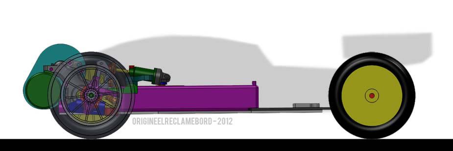
 I haven't had time for the project the last few months, which is a shame, as I was hoping I would've finished building it by now. I have been thinking about the project a lot though. I think I am going to ditch the front shock tower design and go for inboard suspension - it's something I wanted to do from the beginning but thought making it would be complicated. However, it makes a lot of room at the front and it would be cool to try something 'new.' I haven't had time for the project the last few months, which is a shame, as I was hoping I would've finished building it by now. I have been thinking about the project a lot though. I think I am going to ditch the front shock tower design and go for inboard suspension - it's something I wanted to do from the beginning but thought making it would be complicated. However, it makes a lot of room at the front and it would be cool to try something 'new.'

|
|
#44
20-04-2012
|
||||
|
||||
|
Quote:
 ) )Anyway, if you are interested in the components, just drop me a PM.
|
|
#45
20-04-2012
|
||||
|
||||
|
Quote:
|
|
#47
24-04-2012
|
||||
|
||||
|
I just wonder what the will you do when get to the table top ?????
i dont think it will run/jump well. Think like this if it would work someone should have done it alot sooner ... but hey dont loose that faith ... mvh Isobarik
|
|
#48
25-04-2012
|
||||
|
||||
|
Quote:
 Most of them were custom projects. The only reason pretty much no-one has one or knows about the existance of these cars is the fact that RC racing organizations banned the FWD buggies from the 2WD class and put them in the 4WD class, because they wanted to prevent people from having an unfair advantage by driving a rear wheel drive car on high bite tracks and front wheel drive cars on low bite/slippery tracks. Most of them were custom projects. The only reason pretty much no-one has one or knows about the existance of these cars is the fact that RC racing organizations banned the FWD buggies from the 2WD class and put them in the 4WD class, because they wanted to prevent people from having an unfair advantage by driving a rear wheel drive car on high bite tracks and front wheel drive cars on low bite/slippery tracks.And at the end of the day, if it jumps bad, it will be my task to keep on looking for solutions to make it jump well and keep enough forward traction!  For example, on jumps (thus at high speeds), high rear downforce might help the car keep level-ish in the air, whilst at low speeds the weight on the front (and the low downforce due to the low speed) will give the car sufficient traction on it's driven wheels. For example, on jumps (thus at high speeds), high rear downforce might help the car keep level-ish in the air, whilst at low speeds the weight on the front (and the low downforce due to the low speed) will give the car sufficient traction on it's driven wheels.
|
|
#49
25-04-2012
|
||||
|
||||
|
Erm, it may have been mentioned in this thread already, but there is another thread in here by a member called Bloodclod I think.
He made an awesome FWD buggy based on ones that were factory made back in.....the late 80's maybe? So they have been done and they worked ok, design problems notwithstanding. eta: as a matter of fact, here it is. Well worth a look see. http://www.oople.com/forums/showthre...ight=Bloodclod
|
|
#50
26-04-2012
|
||||
|
||||
|
Quote:
|
|
#51
28-04-2012
|
||||
|
||||
|
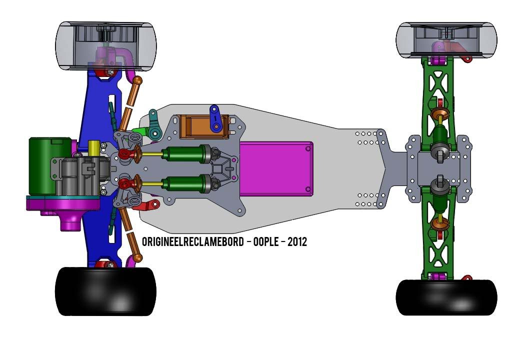
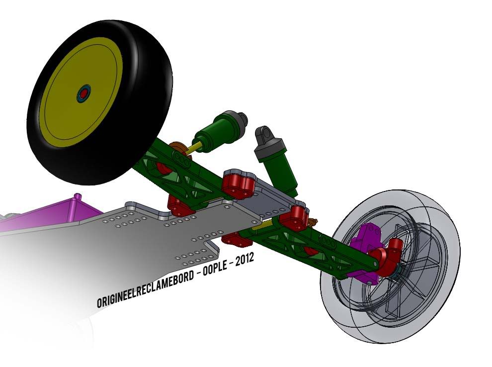
I thought I'd show you guys the first update since... ages!
 I made a mockup on the inboard suspension and body. This layout gives it's own problems, this time not around the gear cover, but around the steering rack and rocker arms. There's not a lot of space to put everything, so I have to re-arrange some parts. However, it looks promising to me. I just need to calculate what geometry I need to make maximum use of the potential displacement of the shocks but also keep track of whether there are springs, pistons and oils to make a good setup at that geometry. Edit: After working on the project for an afternoon, this is the result: 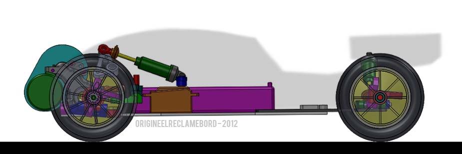 As you might have noticed, the rocker isn't as low and elegantly placed as it first was. But to be fair, that was a long shot. The problem is that the tie rods and the rocker arms 'ideal' position is in the same place. Something told me that might not work in practice I tried moving the tie rods, but there is little room for changes without making the steering geometry kind of knackered. I also looked at moving the rocker arms, preferably forward, but there is no room for that due to the spur gear, motor plate and gear cover. So whatever I tried, the suspension ended up higher. In the end, this is about the lowest I could get it to be. The problem only existed when cornering with the inside wheel pushed up - it's not likely to happen, but I thought it would be best not to limit the suspension's movement by having parts binding. As you can see here below, there is now plenty of clearance between the grey rocker arm and the orange adjuster of the tie rod. 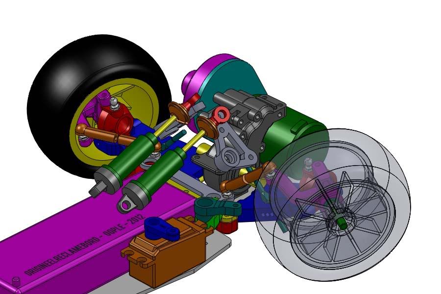 I really like the result of removing the shock tower: It allows for more freedom in setup: There can now be 3 holes for mounting the suspension in the lower arm instead of one, and I can adjust the suspension drastically by using different rocker arms. The weight is further to the middle and I think the centre of gravity won't be affected much in terms of height. And last but not least, look at this front profile!  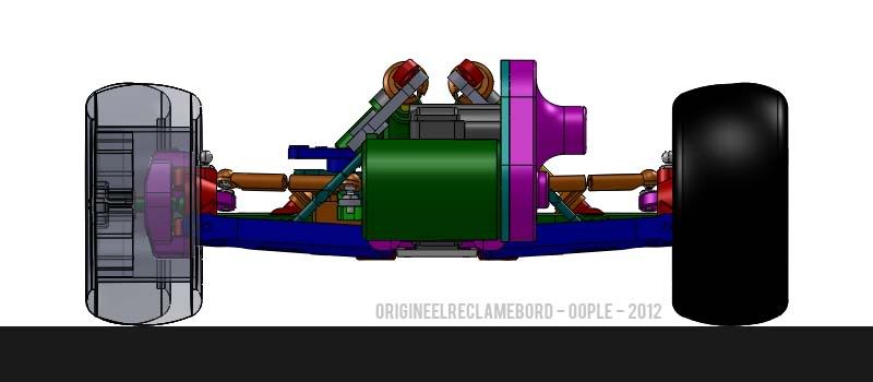 While working on the inboard system I realized I needed to adjust the arrangement of the electronics on the chassis - once again! To accomplish the arrangement below I need a custom top arm on the servo saver, because the standard 201 arm is in line with the lower arm of the servo saver, not perpendicular to it. Unfortunately, the large space between the gearbox and battery is necessary to make the steering rack. However, it does leave some space for weights low in the front of the car, which is nice. 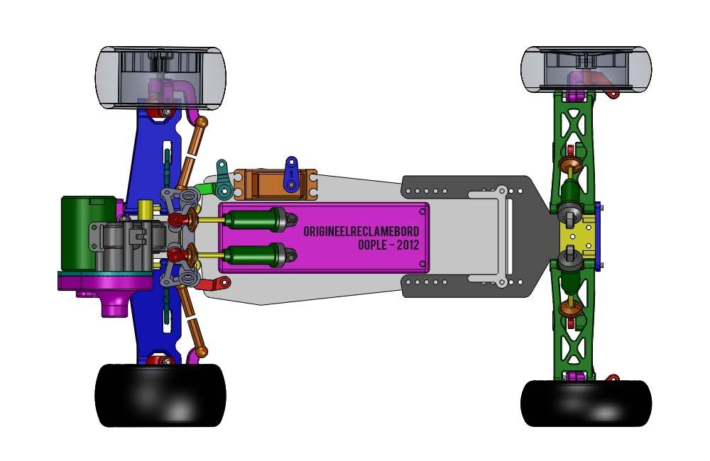 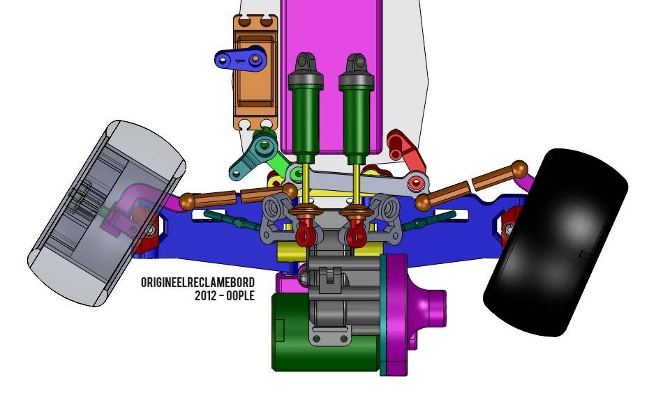 The rear end won't have an inboard suspension system. I've looked at it, but if anything, it makes it more difficult to take the battery out and it doesn't lower the centre of gravity. Using the rocker arms actually made the rear suspension system higher than the shocks when placed at 45 degrees, which they are now. I hope I can use the shocks angled so far down so I can keep a low profile on the whole car. The wing will be mounted low to the small rear shock tower, and there will be a seperate mounting block or plate for the rear turnbuckles and rear tie rods behind that. 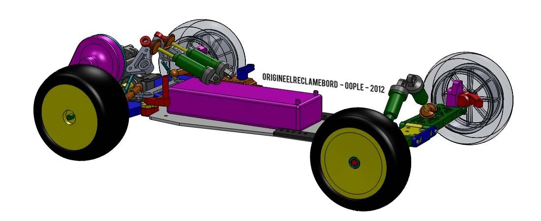 Today has been a day of some drastic re-thinking of this project. First of all, I have some experience in 3D printing nowadays, and I will use this production method for some of the parts, and probably many mockup/first test parts. Secondly, I reconsidered the whole design of an FF Buggy. I even drew up some sketches of an inboard motor FWD buggy with the steering rack and servo on the front, with room for chassis weights to make a good balance. It sounded nice, as if it would solve the problems with finding space for all the parts, but I thought that the space at the front wouldn't be a problem with a compact TRF201 gearbox instead of a Dyna Storm gearbox when I started this project. The only thing the 201 gearbox did is raise the stakes and make the project possible, but not problem-free or easy I'm happy with what I got done today though: The mockup seems to have no issues, so I am now confident enough about how the parts fit together to start modeling all the parts for the inboard suspension.
|
|
#53
29-04-2012
|
||||
|
||||
|
Quote:
I've already seen an FF03 converted to a buggy (Click), and I've did a similar conversion with an FF01: Just using DF01 suspension arms and tub. It drove quite well, but I was looking for something more competitive and serious.Competitive = competition car. I wanted a slipper clutch gearbox, so then you quickly end up in the buggy scene. Since I had a TRF201 already, it was almost a no-brainer to get a 201 as a donor car for this project - more spares for my 201, and I don't have to buy two spares bulks for the two cars!  The XV-01 is indeed a promising alternative, but I'm already too deep into the 201 based design to go back. If I'd really go berserk on this car, I would design my own suspension system from the ground up, driveshafts, gearbox (which would be radically different and would not need a slipper) and chassis parts that have a shape that searches the limits of production techniques - which means I'd also be looking at 3D printed parts for the final car (something I do now as well, but probably not using the freedom of shape on those parts to the max). However, for that I lack money, knowledge and experience. This project is to get a start on that. Develop it, build it, test it, let others test it (a most crucial step to find out how well the car handles and to find areas for improvement) and do the process all over again in the future.
|
|
#55
29-04-2012
|
||||
|
||||
|
Quote:
 Anyway, to come back to your point: I checked yesterday if the upper links would fit. They need to move to the front a bit, but it will fit. It's almost too tight for comfort, but it will have to do The DEX210's inner rear adjusters may help to create a little more room by the way.
|
|
#56
01-05-2012
|
||||
|
||||
|
Update time:
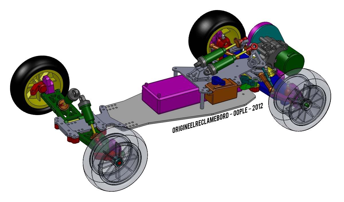   I made a top plate in the front. This has several functions: - Hold the servo in place - Hold the battery in place - Mount for the dampers (through the small mounting block) - Still to do: The block to which the rocker arms will also be partially mounted to the top plate. I also made the inner mounting positions for the upper links on the front of the car. I don't yet have pictures of it, but in the mockup it worked well I've replaced the rear suspension block (which was a TRF201 front suspension block) for DB01 suspension blocks on 4 corners, connected to plates. This makes for more adjustability, and they are easier to mount: I noticed on my 201 that the blocks themselves very much depend on the L10? part (front top frame/mount for front shock tower) to stay in place - the holes don't have threads and are at least 3mm, so mounting it firmly into place needs a very specific construction and part - something I didn't really want as this works for me too! And last but not least, I have been working on the wheelbase adjustability on the rear. It needed to be compact so I can still take the battery out, and to save weight. My thought was that I could slide two small plates over each other, which makes for a compact construction and strengthens the narrow plate constructions in the rear.
|
|
#57
01-05-2012
|
|||
|
|||
|
i know you want the weight over the front wheels to gain traction, but surely you will need to move the battery more towards the rear so it doesnt nosedive off jumps?
__________________
Supatraveller.com
|
|
#58
01-05-2012
|
||||
|
||||
|
Quote:
I understand your problem, and sure in a configuration like this there are compromises to both forward traction and the 'ideal' weight balance for cornering and/or jumping. However, if people manage to make their cars backflip through the air and land on 4 wheels by adjusting their throttle with a car with the weight slightly to the rear, then I think it can too be done with the weight up front, even if it's only 2WD. I managed to make my TRF201 land almost vertically (both nose first and motor first) on the jumps of an average 1/10th scale track. Why wouldn't the car be able to do the same going backwards? I've seen video footage of BloodClod's FF buggy and Grahoo's (TamiyaClub member) FF buggy, and both seemed to manage the jumps pretty decently (even if the jumps Grahoo's buggy made were pretty small). And if physics somehow don't at all work in reverse, then I know it's time to get a bit more creative on the design: Perhaps a system that changes the weight balance during acceleration or on command of a switch will be the answer to the problem, a gyroscope, black magic?
|
|
#59
01-05-2012
|
|||
|
|||
|
Double post, sorry. slow oople today.
__________________
Supatraveller.com
|
|
#60
01-05-2012
|
|||
|
|||
|
You might be right but a car that requires a lot of throttle control to fly and land properly is a pain in the backside to drive. Thats one of the reasons mid-motor is so popular is because they jump nice and level. It will be interesting to see when you get this going.
Maybe adding the ability to slide the battery forward and back will be a good thing to have during initial testing.
__________________
Supatraveller.com
|
 |
| Thread Tools | |
| Display Modes | |
|
|


 Linear Mode

