|
||

|
|
||||||||||||||||||
|
#61
 01-05-2012
|
||||
|
||||
|
Quote:
These vintage fwds could lap Yatabe faster than Masami with his RC10.
__________________
Visit my showroom 
|
|
#62
02-05-2012
|
||||
|
||||
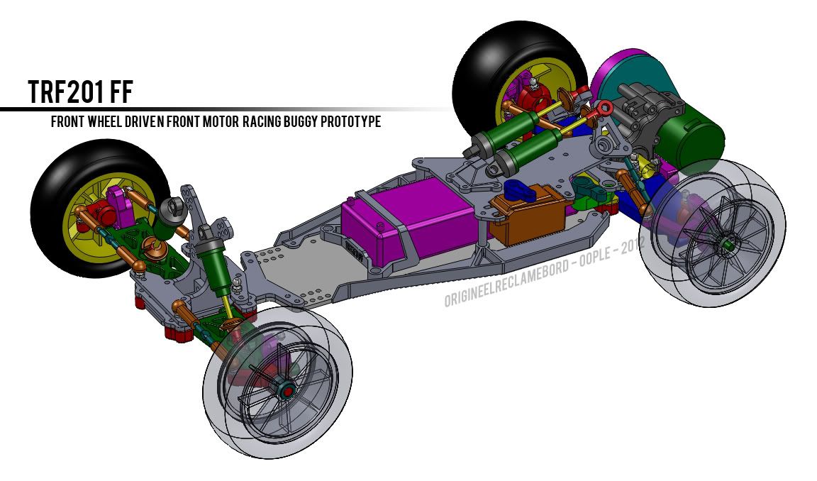 Time for another update! There is only one big part left to model  It's the block to which the rocker arms mount. I think I'll use TRF201 front axles or something similar as an axle for the rocker arms to rotate on - then there are some small things to model, like the mounts for the axles which the steering arms rotate on, and I got a very nice idea to add weight very low in the front of the car. It's the block to which the rocker arms mount. I think I'll use TRF201 front axles or something similar as an axle for the rocker arms to rotate on - then there are some small things to model, like the mounts for the axles which the steering arms rotate on, and I got a very nice idea to add weight very low in the front of the car.List of updates - New parts: - Mounting block for rear suspension parts. This part mounts is a mounting block for the rear shock tower, a plate for the tie rods and a plate for the upper links of the rear suspension. - Rear shock tower. This includes holes for the wing mounts - these will be TRF201 wing mounts. You might notice the holes are pretty low, this is down to both issues with space and the fact that I think the wing should be low  - Rear tie-rod plate. - Rear upper link plate. - Sidepods (120mm total chassis width). The sidepods replace the earlier 'wide' chassis. The vertical edges will make a better fit for bodies and better protection for the electronics. The sidepod also lifts up the edges slightly, so the chassis doesn't bottom out easily in corners. It also makes the main chassis plate cheaper. - Battery retainer. Unlike many battery trays, this one is suitable for pretty much any stick battery, wherever the the wires exit. - Name. Like any car this needs a name. I could have gone for outrageous names or a name ending with 'V.3.0.6.2.01 Beta' or 'Gen 5', but even though I worked on it a lot, I found peace in a much simpler name  'How about TRF201 FF?' 'How about TRF201 FF?'List of updates - Updates parts: - Tweaked/optimized rear suspension geometry (for neutral base setup in terms of change in toe and camber throughout the suspension's movement, but with plenty of room to adjust) - Narrower chassis plate (81mm instead of +/- 110mm). This is for several reasons. I noticed I needed an 'even' wider chassis than 110mm to fit electronics comfortably. Widening the chassis would make it more expensive and stiffer (and my prediction is that it doesn't need to be that rigid). I thought sidepods would be a suitable alternative. 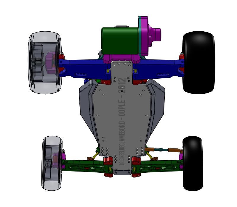 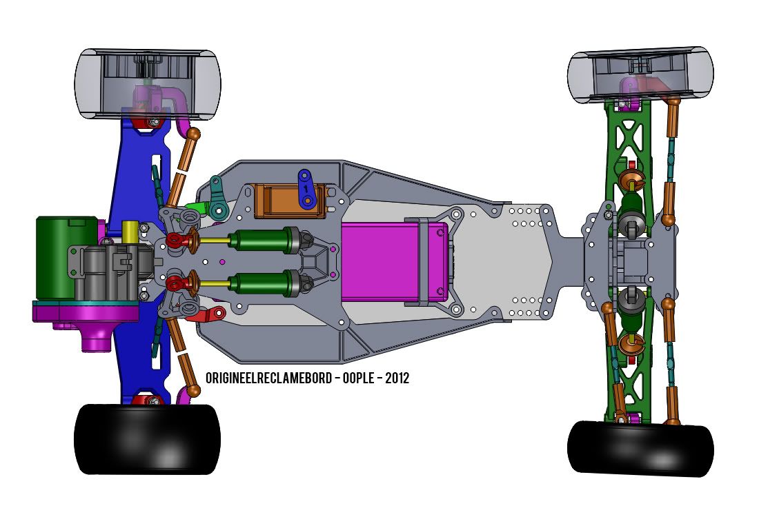 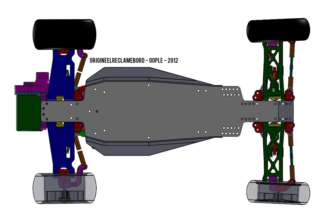 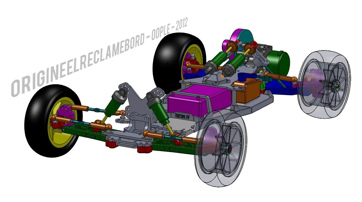 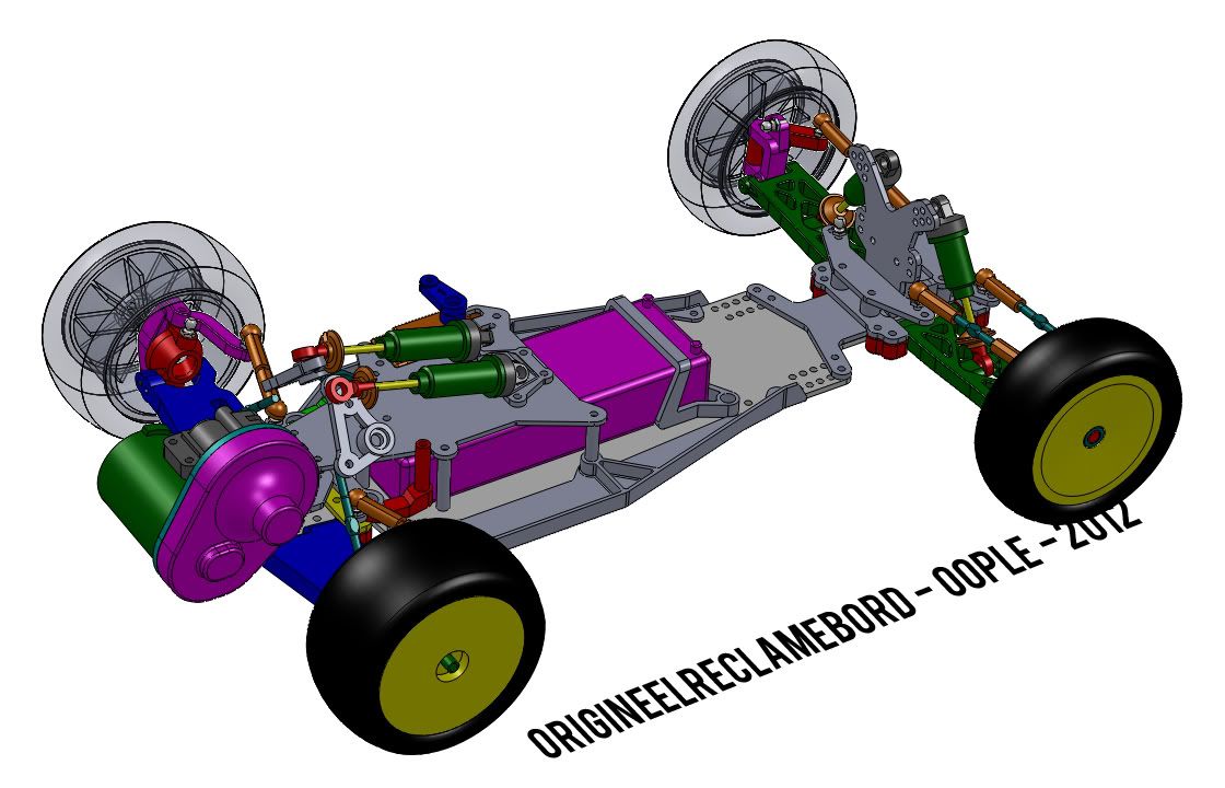 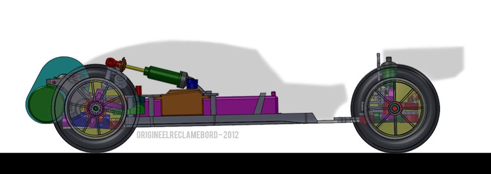 I think I'll contact Team Xtreme for advice on the rocker arms and whether it's likely the geometry of the front suspension system allows me to use existing stiffness 1/10 buggy rear (or if it needs be front) springs and 'regular' damping setups - Or can someone else help me with this?  When all this looks allright I'll have the parts 3D printed and cut the plates in a laser cutter from plastic. It will be for mockup and a test in practice to see how the geometry runs. IF it gets the green light on every single of these steps without major adjustments I should be able to get the plates cut from carbon and some of the parts machined from carbon reinforced plastics or metal. Quote:
 That said, one of the goals of this project is to make an FWD buggy that has the potential to go fast around a track. That, and to form a base to get data from driving FWD buggies, as there is only basic data available on what forms a good FWD chassis (such as most of the weight being in the front for forward traction). Whether it will be competitive with the right setup and in the hands of the right driver or in the hands of every driver and with every setup is difficult to say beforehand. That's why I'm building one to find out, and to see where there is room for improvement 
|
|
#63
02-05-2012
|
||||
|
||||
|
I would really look at the rear end suspension having trailing arms rather the more tradional buggy arms, the cars are very light at the rear and i don't think what you are planning will be the optimum way to go. You will need very light damping / spring and from everything i have seen trailing is the way to go.
Also with the tralining arms you will also be able to lower the c of g nicely as the shocks will no long be sticking up in the arm  and its very simple to setup camber and toe via turnbuckles which attach via the trailing arm. and its very simple to setup camber and toe via turnbuckles which attach via the trailing arm.Also for us to run this car in the uk, it can be no more than 250mm wide which i think could be a issue if your using a 4wd front end with rear hubs fitted, and rear tires would have to be fitted at the back of the car for it to be legal. Btw if you get stuck for making the plastic parts give me a shout.
__________________
Jonathan | Atomic-Carbon
|
|
#65
02-05-2012
|
||||
|
||||
|
Quote:
Grahoo's Hotshot Team Kassanova K2 (Link 1, Link 2)
|
|
#66
02-05-2012
|
||||
|
||||
|
Quote:
Thanks for the advice, and for your heads up on the production of parts Just a question: Do you think it would be a regretful decision or a mistake (performance wise) if I stick with the double wishbone suspension? The thing is, I have nearly finished the car now. The reason I have chosen for a regular layout at the back (earlier in the project) is for the reason that I know little about setting up cars - for me it's a way to keep the conventional bit in the car and be able to talk easier with people about setups for this car. However, with the change on the front suspension I guess that's not really the case anymore for the car anyway. As for the width: I know about the 250mm rule, it is why I have designed custom front suspension arms. I should be able to use 70mm (DF-03 length) universal shafts on the front end, though it will be a tight fit and might require the use of shortened outdrives and/or a gear diff (so I don't have a screw and spring in the outdrives in the way of the uni's). The wide rear tire rule is a problem though - especially with the current rear suspension Even though I don't run in the UK, I was hoping the car would be 'legal', I thought getting it less than 250mm wide would have been my biggest issue with regards to the rules - besides the fact that most regulations state it must be run with the 4WDs. It's a strange rule though, why would anyone chose to fit narrower tires on the rear except for when you'd be driving an FF car?
|
|
#67
03-05-2012
|
||||
|
||||
|
Update:
I have to thank Jonathan/OldTimer for notifying me of the rules of the BRCA with regard to the rear wheels/tires. It seems in the UK you are limited to using rear tires on the rear. However, the EFRA (and the Dutch RC Sporting Organisation which bases it's chassis regulations on that of the EFRA) doesn't seem to have rules restricting the use of the rear wheels to wide ones. Of course it may be possible to enter the car as an RWD buggy with rear wheel steering and set up to drive around the track backwards real quick However, I think it won't take long before they ban that sort of 'F1 style' of stretching regulations if you'd try that. Therefor, here's an alternative version to the car using DB01 uprights and C-hubs on the rear as well. It's my intention to build and test both types: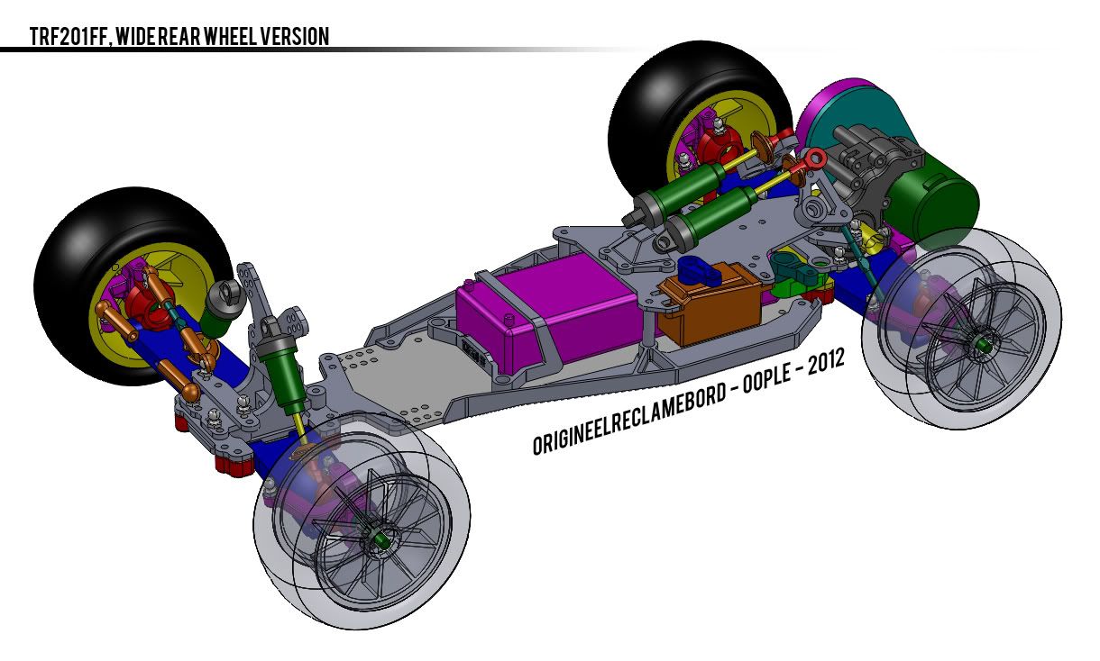 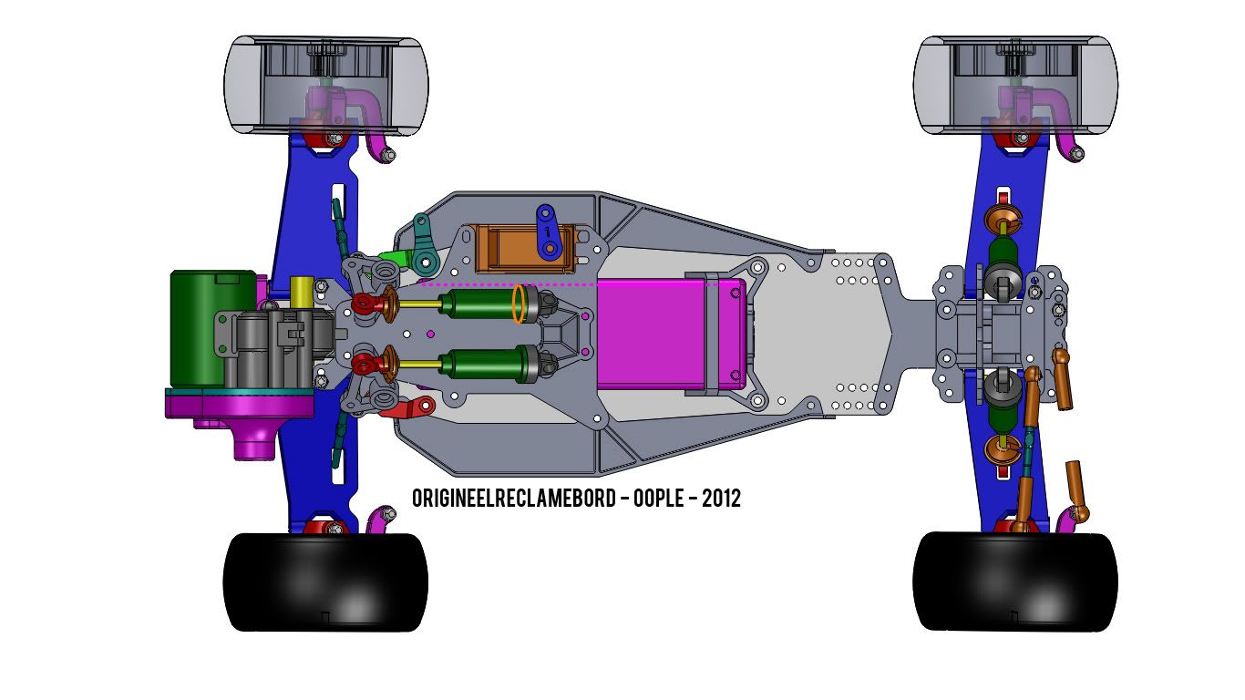 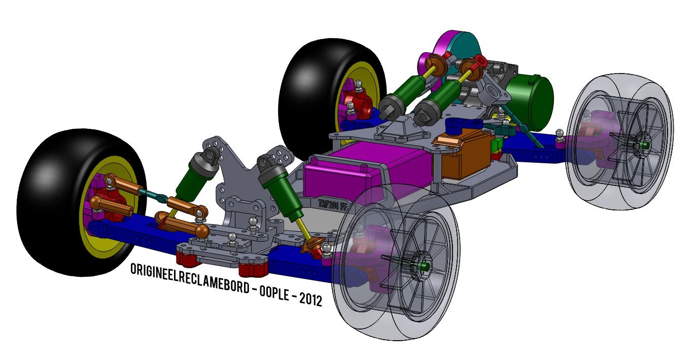 I prefer the narrow wheel version, both for expected performance (you don't need that wide wheels on the rear I think) and aesthetics. But if this change will help it to be legal on the UK events the changes are worth it!
|
|
#68
04-05-2012
|
|||
|
|||
|
Nice work. One observation I have regards the front shock bell cranks. I wonder if the large angular change in direction coupled with the quite short lever arm might result in some unwanted high forces about the pivot point. Don't sacrifice strength here, and make sure everything is a good fit to help prevent any kind of motion 'lock out' that might occur through misalignments etc. A larger input lever arm would help perhaps.
The cranks on the Pred take quite a hammering because you have a large force leverage at that point. Keep going, it looks interesting.
|
|
#69
04-05-2012
|
||||
|
||||
|
Quote:
Quote:
Quote:
If your shock is mounted on the rocker at 2 times the distance from the pivot as the link mounting point, if the link rises 3mm the shock will be compressed 6mm, and you will have 2 times the spring rate pushing on the link. The only way to be sure you have it sorted is to experiment. The X11 has machined rockers as the geometry was already developed from the original Predators, and TTech themselves didn't get it right first time which is why we had the GP rockers, which were the original plastic rockers with a carbon fibre plate on top to move the link mount to a different angle on the rocker. You can always do the same if needed, make the rocker a bit smaller and use a carbon fibre plate to attach the link or shock mounts to the rocker, so you can easily cut and drill new plates if you need to change the rocker geometry. If you
__________________
Visit my showroom
|
|
#70
07-05-2012
|
||||
|
||||
|
Thanks for the explanation
The part on the rocker arms is extremely helpful. It confirms what I thought about the distribution of the forces to the damper. I will definetley try out several rocker arms and types of geometry to get it to work well. The regulations are just something I have to accept - running rear tires might now be necessary (or optimal for that matter), but on the other hand, if the project turns out to be (extremely) succesful, lighter wheels and/or inserts could be developed for it too. Quote:
|
|
#71
07-05-2012
|
||||
|
||||
|
Yeah I'm going to agree with an earlier comment.
You should definitely use the excellent work you have done so far as the basis for a standard RWD chassis as well, if only as a sideline. The FWD idea and the work you've done is great and I hope you get it done soon and see how it goes, it's just looking at it, it would also make a sweet aftermarket RWD chassis as well with a few bits and bobs changed. Looks a little Durango-ish, I think it's the side pods.
|
|
#72
09-05-2012
|
||||
|
||||
|
just been looking at your design and i understand that the inboard suspension design is better becouse of space but the idear of inboard suspension is to lower the C/G but its a compromise as the suspension doesnt work as well as the conventional way. plus does look cool
.ive looked at where the shock absorber are on your car and plus all the extra weight to get the shock absorber to where they are and it seems to have a much higher C/G than a conventional front suspension so it seems to me that having inboard suspension in the way you have done it is to much of a compromise. also with my experience with a fwd touring car i used to race yokomo yrf2 sp and also am running atm a tamiya m05 ra and having trailing arms rather the more tradional suspension arms does work alot better. but even though i think there are a couple of things wrong your work on the car does look sexy
|
|
#73
21-06-2012
|
||||
|
||||
|
It's been a while since the last update due to 2 things:
1. Busy with stuff for school 2. My hard disk crashed (and became unsalvagable too), and I lost my last 4 months of work because I didn't make a backup... ...Luckily this project was one of the very few things I did have a backup of! Now that I have had all my deadlines for school for 2011-2012, I can re-focus on the project. A month of not modelling on the car gave me time to think about the comments and advice I got for the design, and I decided I wanted a couple of things changed. They are mainly with regard to the weight balance. A shorty LiPo to shift the weight balance without having to widen the chassis. Then secondly, a trailing arm system. In the new layout the only 'weighty' parts on the back half are the dampers, so the weight balance is guaranteed to give good forward traction. Jumping it will be more of a challenge probably, but I think practice will be key to success there       As you might have noticed, the first few pictures have DB01 uprights and caster blocks on the rear. However, Jonathan gave me the advice to make a one-piece arm, using slight negative camber and some toe-in. In the end 2 degrees of toe-in on each side and 2 degrees of negative camber is the setup on the rear. The rear arms have approximately 65mm articulation, which should be more than enough!
|
|
#75
21-06-2012
|
||||
|
||||
|
Quote:
I have a portable hard drive, but I was too busy to make the backup when I remembered myself about it, and when I wasn't too busy I forgot!  Stupid of me to not MAKE time for it. Stupid of me to not MAKE time for it.As for the car, I think you mean the Yokomo YR-F2? 
|
|
#77
23-06-2012
|
||||
|
||||
|
Quote:
 I wish I'd tackled something like this for my CDT gcse project 18 years ago! a couple of things you might want to consider: 1. where's the x-axis COG? at the moment it looks like there's a lot of weight forward of the front axle line - this might be best for packaging as it allows space for the steering bell crank mechanism, but it may cause excessive fore-aft weight transfer under breaking and turn in, resulting in initial understeer and snappy lift-off oversteer when the rear end quickly unloads (the front axle becomes the pivot point for the moment of inertia). 2. how about extending the main chassis plate past the trailing arm swivel blocks so standard length stick packs can be accommodated? this additional chassis material could also be used for weight mounting to pull the COG forward or backward along the centreline as desired. but these are just suggestions - ultimately, it's looking amazing at this stage. you should be very proud indeed
|
|
#78
23-06-2012
|
||||
|
||||
|
That looks much better, I think it would be nice to have a easy quick way to adjust the toe in on the rear as it will be a quick way to change the balance of the car, and perhaps some more mounting points for the rear shocks to start with until you've run it a few times and know what works?
|
|
#79
29-06-2012
|
||||
|
||||
|
Thanks for the great response and the advice
The design work of the first prototype (to be built) is almost done now. I'm sure that if the progress is good and the chassis layout looks promising, there will be time and budget to make things like adjustable toe and camber on the rear end happen,and I'm sure the weight balance will be one of the main things on the car to be tweaked with. If it turns out it is 'necessary' to test a stick pack LiPo, I can make a new brace for the battery By the way, here is another update: 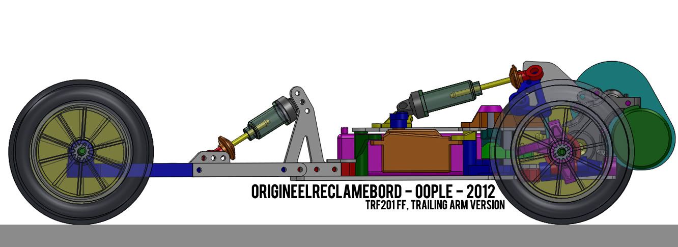 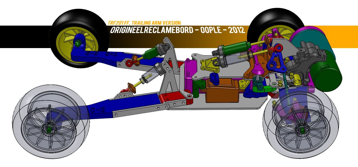 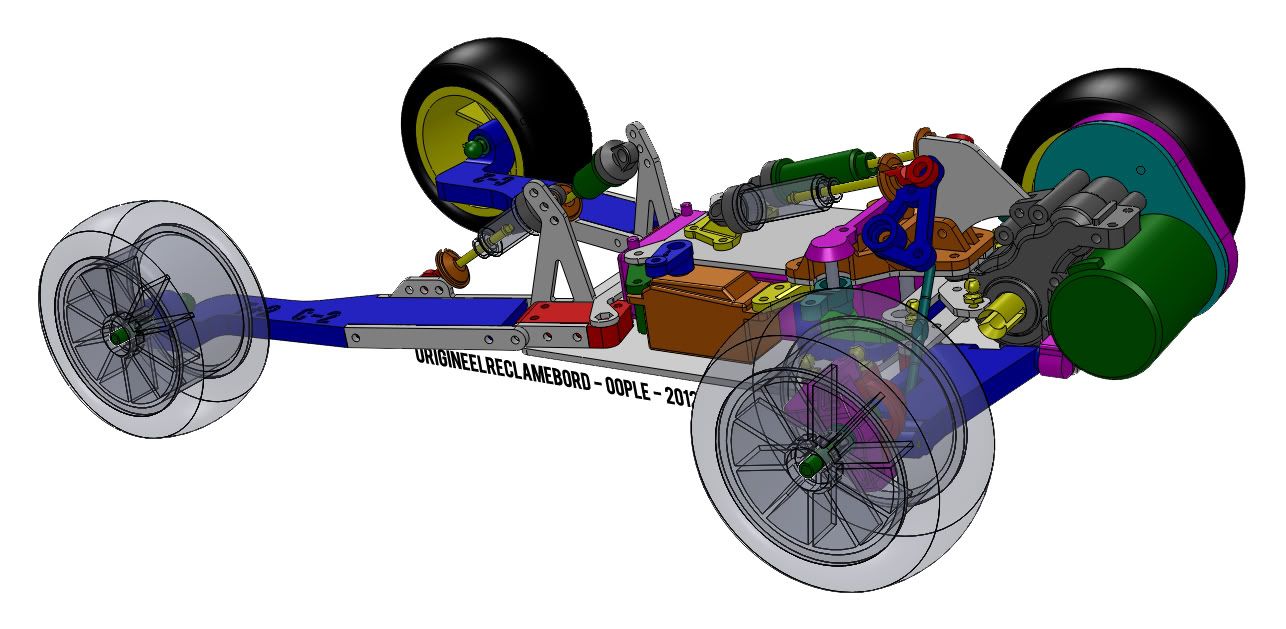 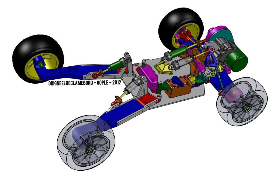 First of all, I made a new mounting system for the servo. This allows for mounting the servo lower (thus having a lower CoG), and a cheaper conversion for servos that deviate too far from the Savöx SC-1251MG's dimensions. I also made some good progress on the steering and front suspension assembly: I made the frame pieces that hold the rocker arms and their axles, and holds the top mounts for the steering arms. Lastly, I made a plate that connects the gearbox with this frame piece as a reinforcement to the chassis. This plate is the 'shark fin' on the car. I made it higher than the rocker arms to (hopefully) protect them in a crash.
|
|
#80
29-06-2012
|
||||
|
||||
|
Quote:
Although Bloodclod has closed his youtube account, I have found a copy of his video of his FF in action and uploaded it here.
__________________
Visit my showroom
|
 |
|
|


 Linear Mode

