|
||

|
|
||||||||||||||||||
|
#1
 22-09-2009
|
||||
|
||||
|
Just finished my build and to be honest I'm scratching my head to figure out a neat install for my radio etc. Any tips from you guys or pics would be mint. Its tight as we all know but I'm unsure about where to put my servo wire and which way round to fit my speedo(sxx). Thanks guys. I just dont want to make a bollox of it. Cheers.
__________________
 PBM Racing 01773 769323 TEAM XRAY RC DISCO 
|
|
#2
22-09-2009
|
||||
|
||||
|
Hey Si, Well you saw mine at the weekend. Thats how Adam wired his too and his was SXX.
As for the servo wire. Mines pretty long (ooher!) So it went better, exiting from the receiver side, and going all the way round the back of the servo, to the motor side, and back in front of the servo to the receiver....if that makes sense. lol it created less 'bunched up' wires all in the same place. You can always shorten it and take it directly to the receiver. The wire will fit rount the servo saver posts without it affecting the shell fitment.  I'm actually going to re-wire mine...again. Cos I got quite a bit of interference in the final. But its a case of suck it and see. If it fits then its good, if not then try again. lol When I've re-wired mine I'll post some pickies.
|
|
#5
22-09-2009
|
||||
|
||||
|
I have the same problem here keep scratchin my head thinking how the hell is this going to fit.
Servo wire greet but the way the wire goes it rubs slighty against servo saver. This is what I'm trying to fit in the car LRP SXX KO Rec 301 Ko Servo Low Profile LRP x12 6.5 I've done few attempts but looks so messy. Any chance some of you guys got any close up pics of your wiring an it installed
__________________
http://www.pbmracing.co.uk/ Kyosho MP9 TKI2 Team Orion CRF US edition & Team Orion CRF Alpha 5port Kyosho ZX-5 FS2 Kyosho RB5 SP2 LRP SXX TC & Brushless X12 Speed Passion
|
|
#6
22-09-2009
|
||||
|
||||
|
Its done! Looks ok. More room than you think. Its tight but do-able. Gotta make sure nothing rubs the prop or spur. I need to extend the wires to the power cap so it will sit where I want it to. Its easier cos you can mock it up and take the speedo and motor out to solder. Much easier. I'm iking this car a lot! I expect I'll re-wire it 3 more times before I settle on my final install but so far its going well. Just need a shell now and were up and running.

__________________
PBM Racing 01773 769323 TEAM XRAY RC DISCO
|
|
#7
22-09-2009
|
||||
|
||||
|
Quote:
Any chance some pics of your layout
__________________
http://www.pbmracing.co.uk/ Kyosho MP9 TKI2 Team Orion CRF US edition & Team Orion CRF Alpha 5port Kyosho ZX-5 FS2 Kyosho RB5 SP2 LRP SXX TC & Brushless X12 Speed Passion
|
|
#8
22-09-2009
|
||||
|
||||
|
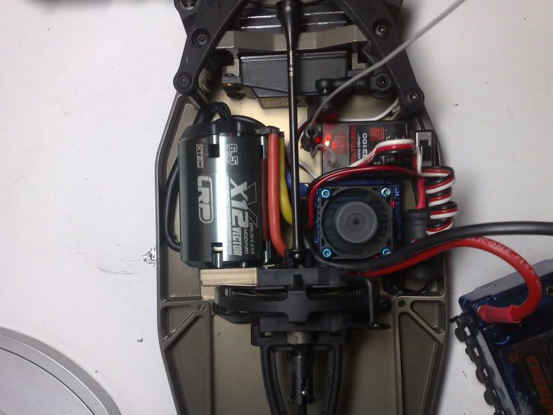
I just re-wired mine, and put the motor how Chupers has his, BUT the contacts hit on the shell and stopped the shell being fitted properly. So I've put a small blister on the shell so it clears the motor contacts.
The Speed Passion motor has larger tabs than the LRP motor so it does rub when its that way. But I prefer it that way up. I've now extended the pt cable and put it at the side of the cells, and have now put the power cap between the motor and speedo, and have tried to keep as much of the wires away from the receiver, to see if this was the cause of the interference. When I get some light I'll get a pic.
|
|
#10
23-09-2009
|
||||
|
||||
|
I'll have a go with it tonight to see what mine should drive like
|
|
#11
23-09-2009
|
||||
|
||||
|
You'll be lucky. Its not a runner yet. Only just putting set-up onto it. Shocks have no oil and not soldered battery connectors yet as unsure of body clearance. It looks awesome tho. Cant wait to run it.
__________________
PBM Racing 01773 769323 TEAM XRAY RC DISCO
|
|
#12
23-09-2009
|
||||
|
||||
|
Best to solder the batt connectors at a right angle. Straight up does interfere with the shell. And we don't want that!

|
|
#13
23-09-2009
|
||||
|
||||
|
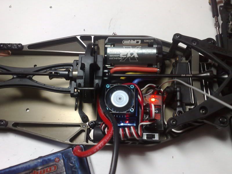
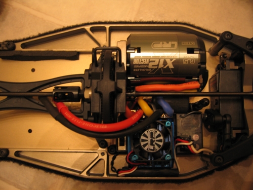
This is mine, appologies for photo quality.
It does look a bit 'mish mash' as some wires intertwine, but its all clear of the prop and it hasn't actually got too many wires over the receiver.
|
|
#16
25-09-2009
|
||||
|
||||
|
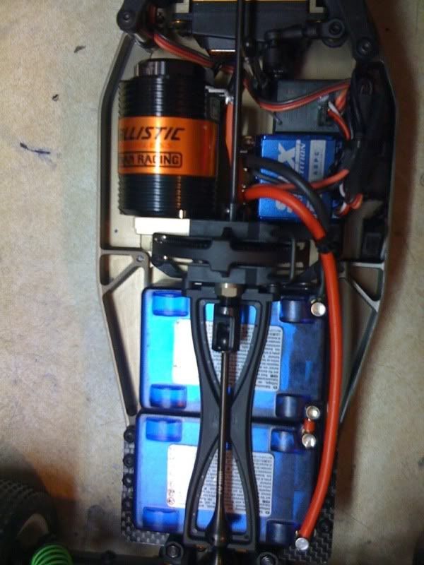
Sweet idea with the link wire on the cells Si! Very cool.
|
|
#17
25-09-2009
|
||||
|
||||
|
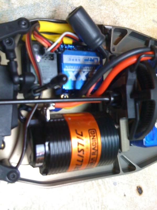
Here's mine
   Fiddly but worth it in the end  Tim
|
|
#19
26-09-2009
|
||||
|
||||
|
I thought it was Mine at first Nick
 Its a bit tricky but the best thing about it you can take the electric board out and motor and solder them up with ease. Tim
|
|
#20
27-09-2009
|
|||
|
|||
|
Can I ask how everyone is routing their servo wire. I'm using a full-size KO servo and it seems that the options for routing the servo wire are a bit thin. You've got to dodge either the main layshaft by taking it round the back or the steering rack.
Has anyone found a neat solution? Appreciate your help. Mark.
|
 |
|
|


 Team Durango


 Linear Mode

