|
||

|
|
||||||||||||||||||
|
|
|
#1
 07-06-2018
|
|||
|
|||
|
I have been building a custom chassis for a clodbuster for a while now, thought I would share on here if anyone is interested? im about half way through.
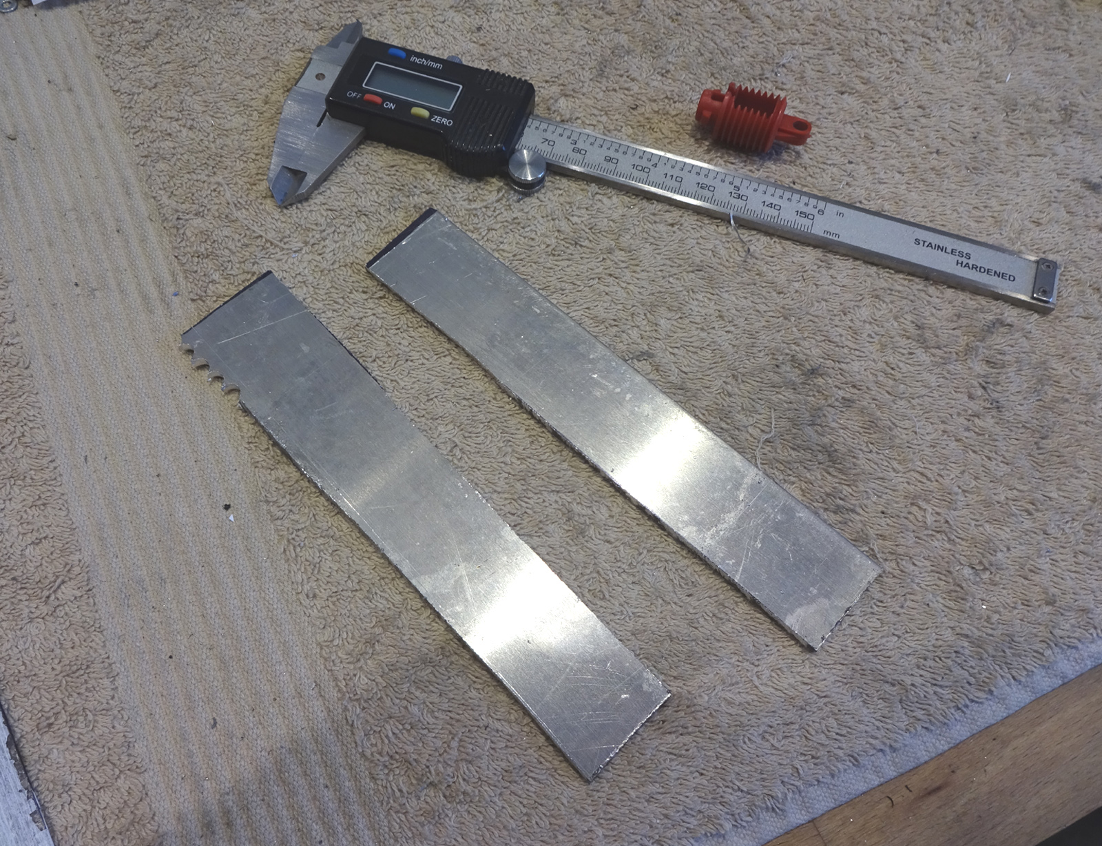
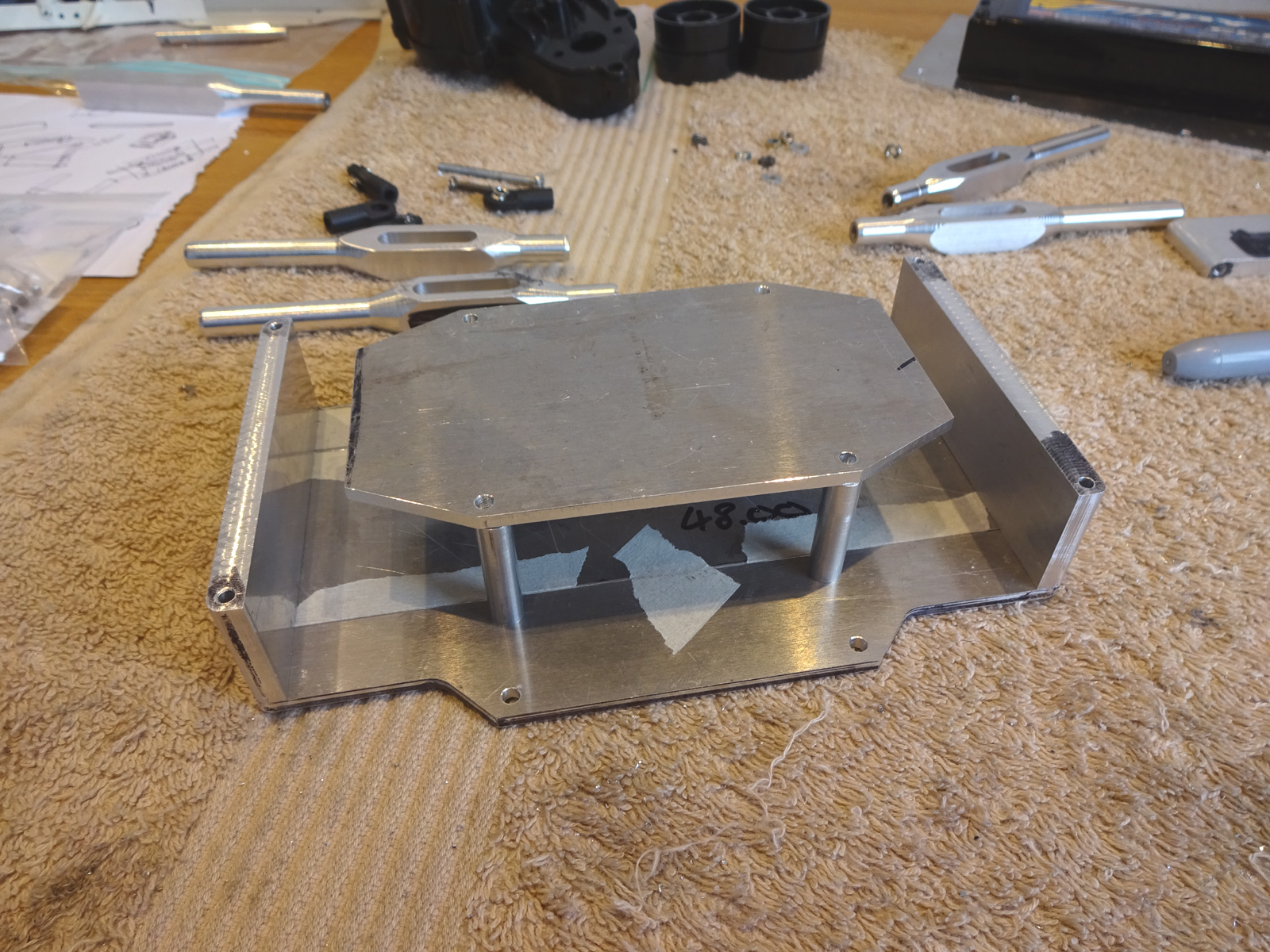
 First thing is top link mounts for the Clod gearboxes. Not much available to buy, I did see a design I like thats not made anymore, so im making that. Cardboard mock up seems ok, uses the existing holes in the gearbox, making it out of 6mm plate, then spacing it 2mm from the gearbox so its centered. 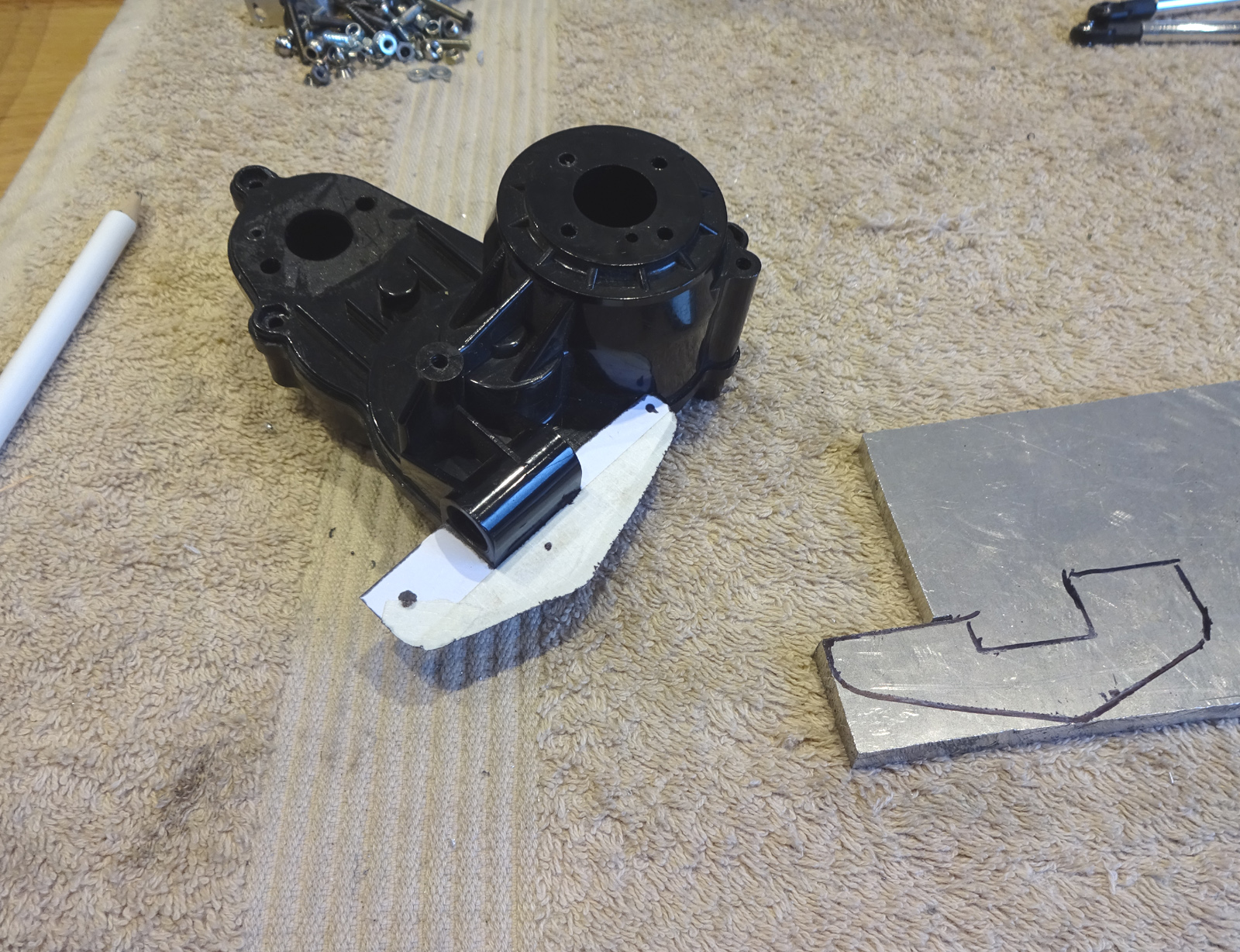 Cut 2 out roughly, at the same time, then got the holes in the right place so i could bolt them together and machine them at the same time. 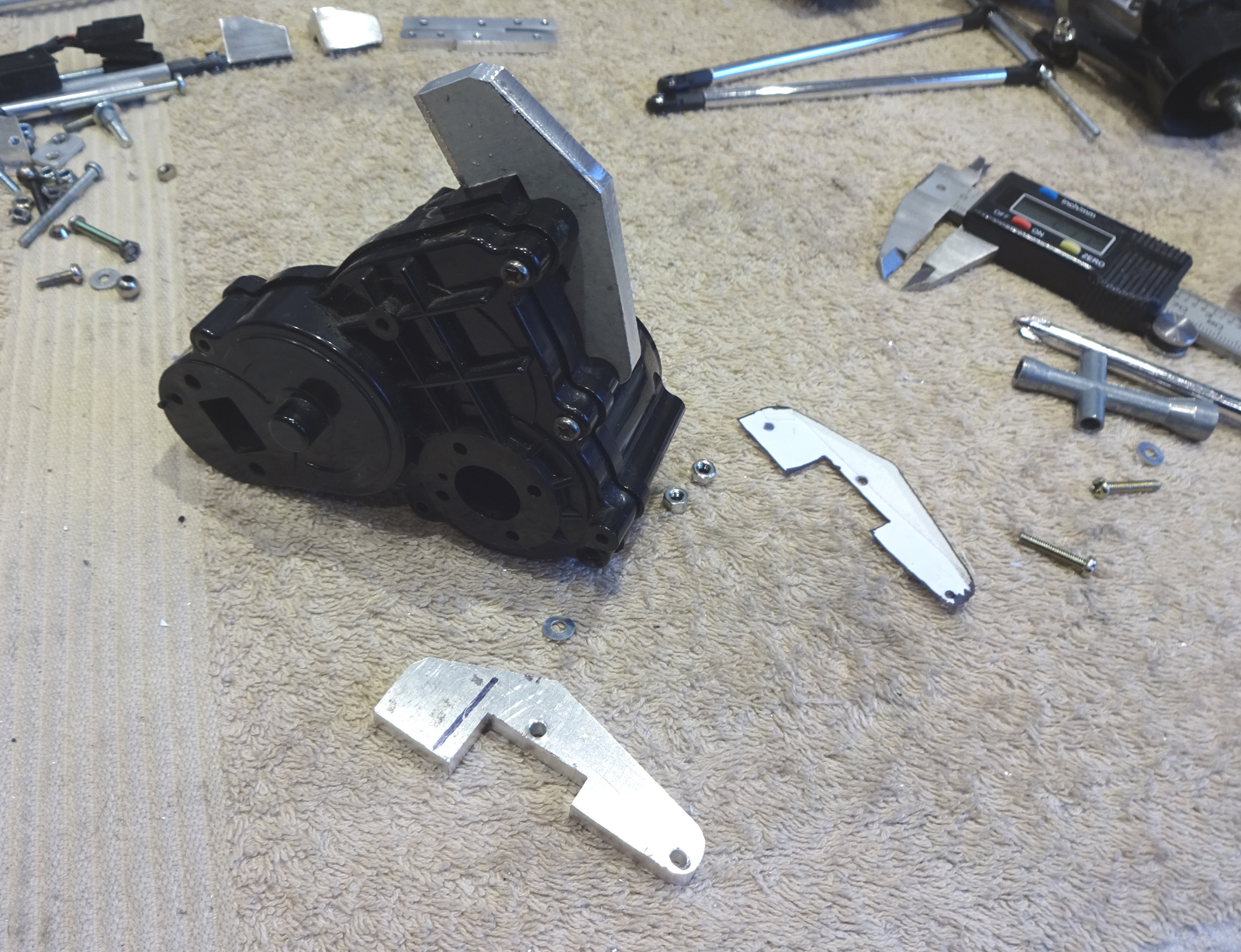 The screws normally go into the gearbox and into nuts where the plate is now. So the plan is to put the screws into the other side and have the nuts where the screw heads are now. These little dudes go in where the recesses are for the nuts and then space the plate out 2mm at the bottom and 2.9mm at the top (yes I found out the gearbox isnt totally even there). 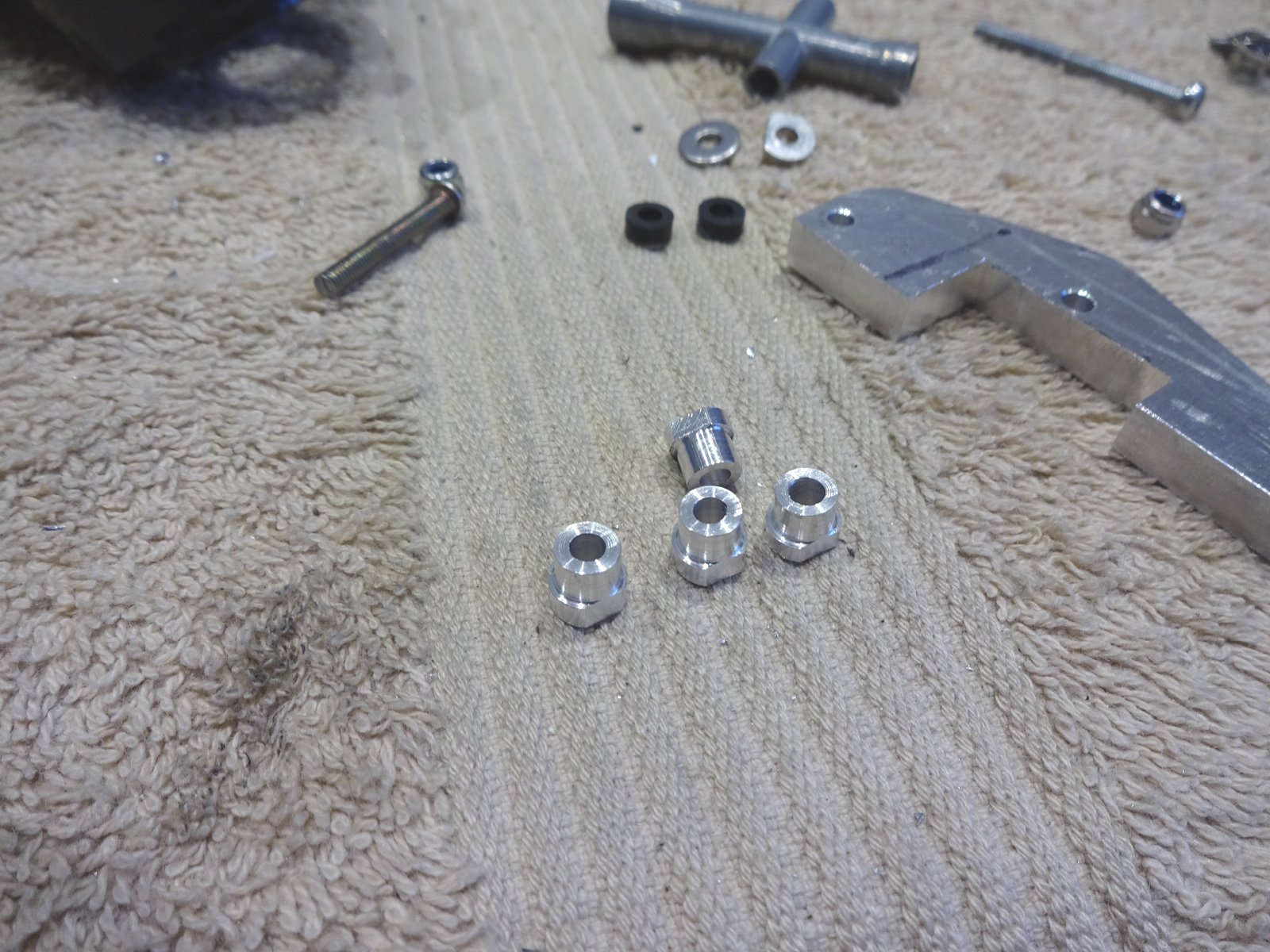 All square now, you can just see the top spacer has to be 0.9mm fatter. 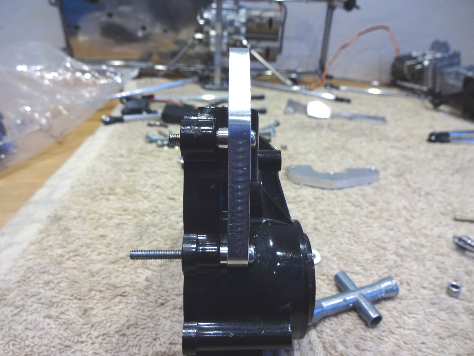 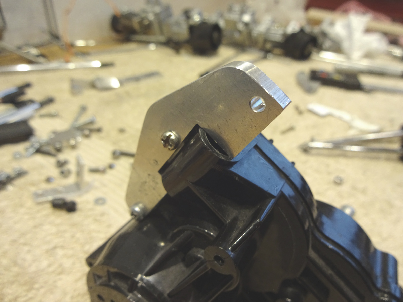 Polished up the top lunk mounts 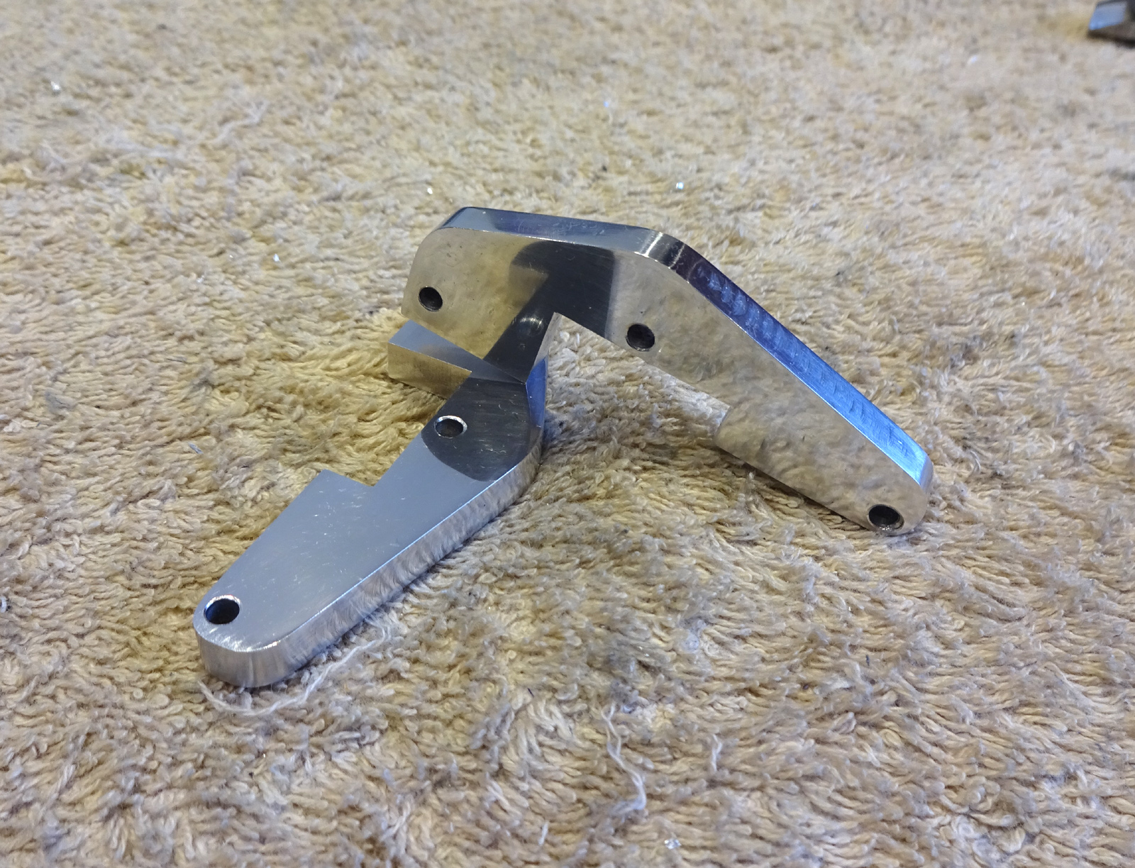 The design I have in my head is a bit complex so its time for the cardboard, something double deck: 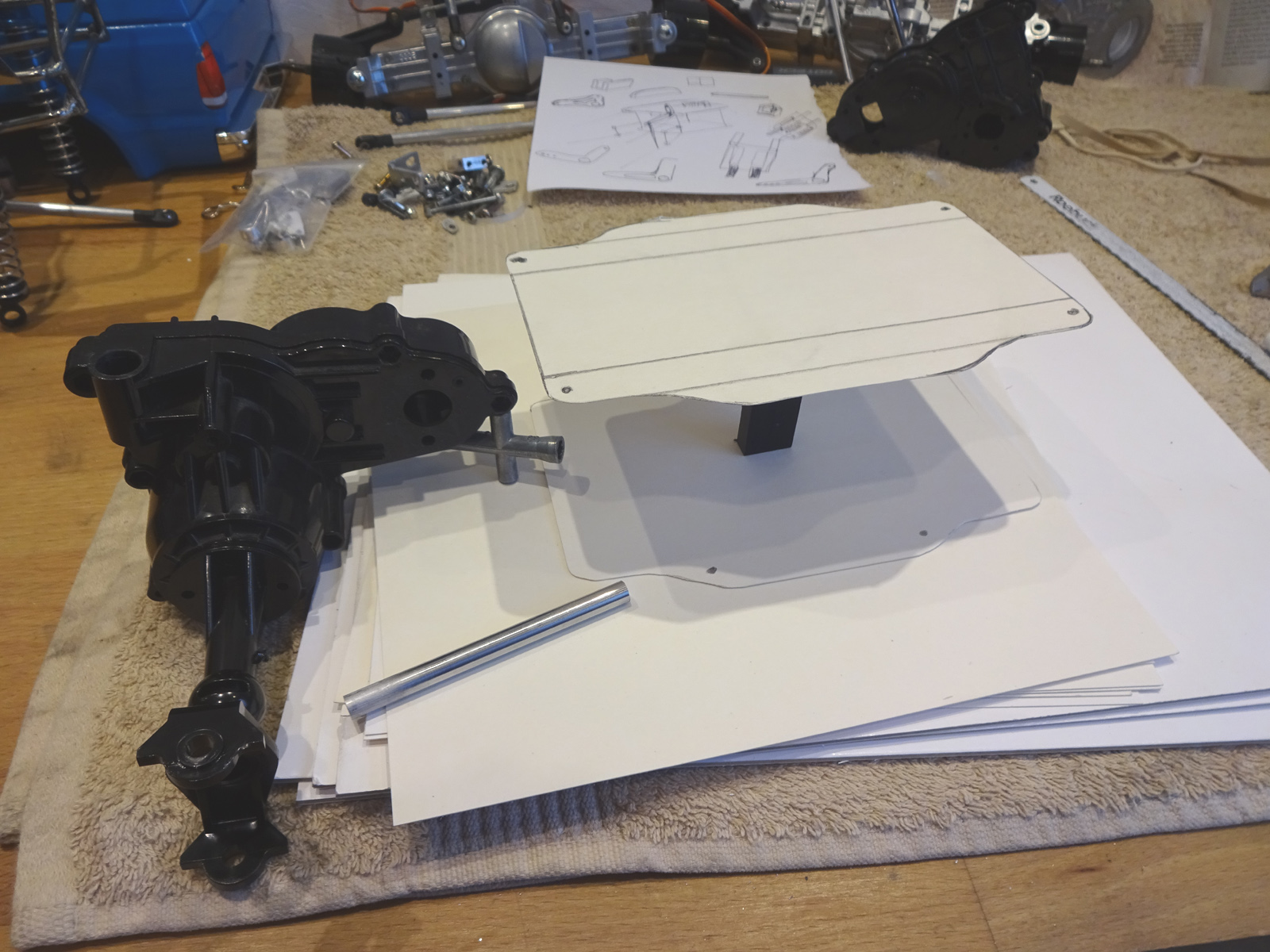 Then I had a cup of tea, then got out the sticky tape....... 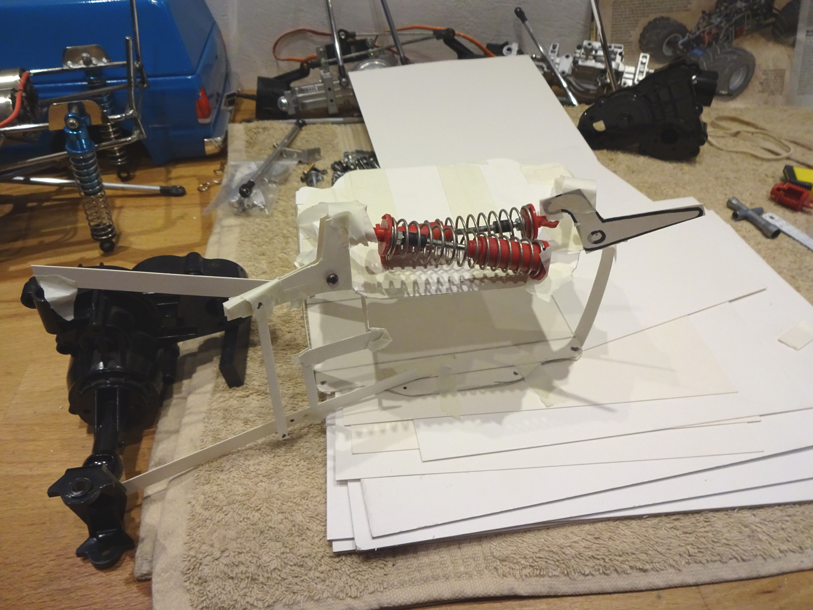 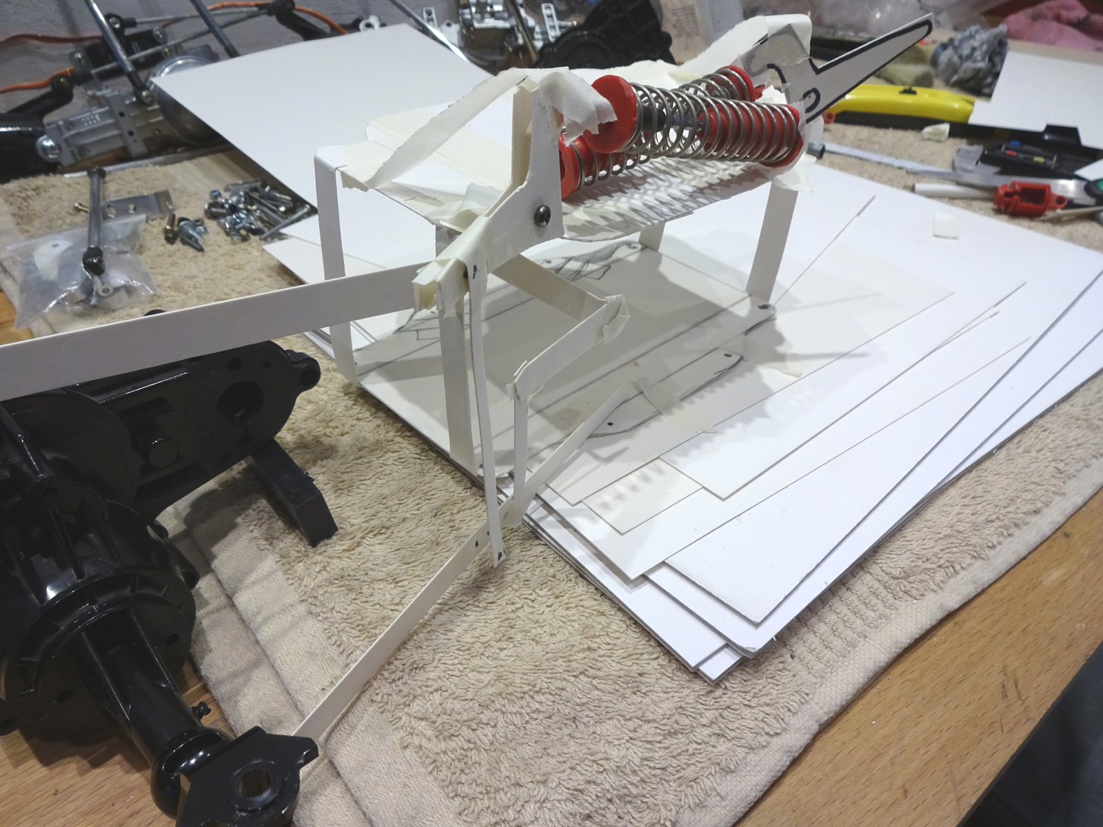 yes .... so...... cantilevers, shocks mounted side by side on the top deck, sway bar below that, with the battery mounted long ways, and fitted through the bottom of the lower deck. 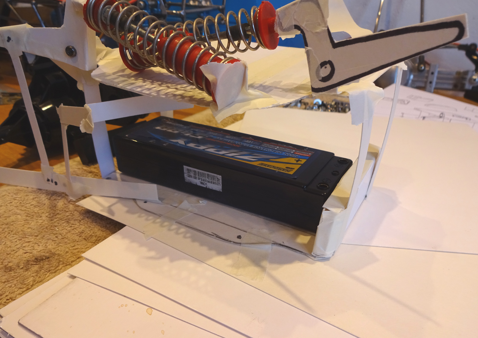 so top middle and bottom deck, like strike it lucky 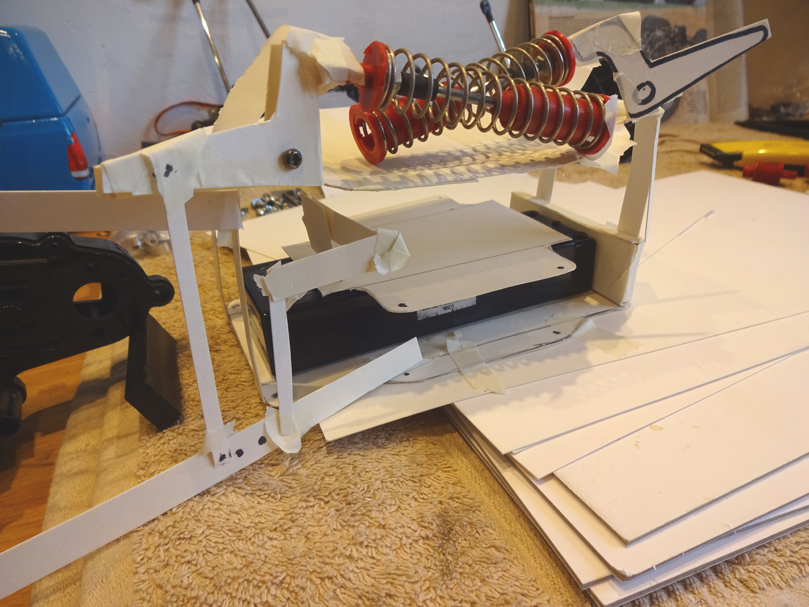 I know it looks a mess but im sure things will work themselves out  
|
|
#2
07-06-2018
|
|||
|
|||
|
Started on the lower deck
 screwed them together and milled the flats at the same time   The idea is the battery will load from the bottom 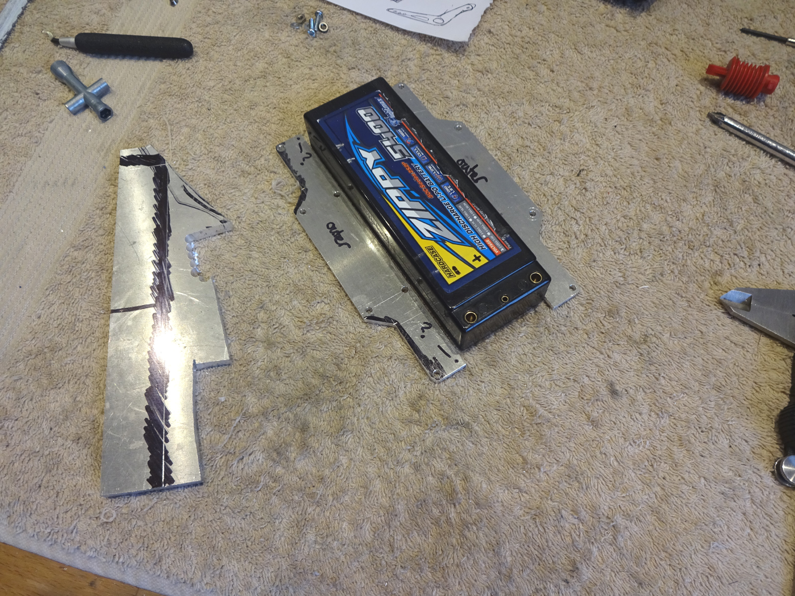 my little mill 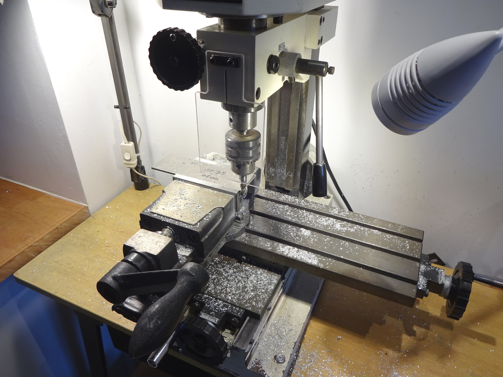 all spot on  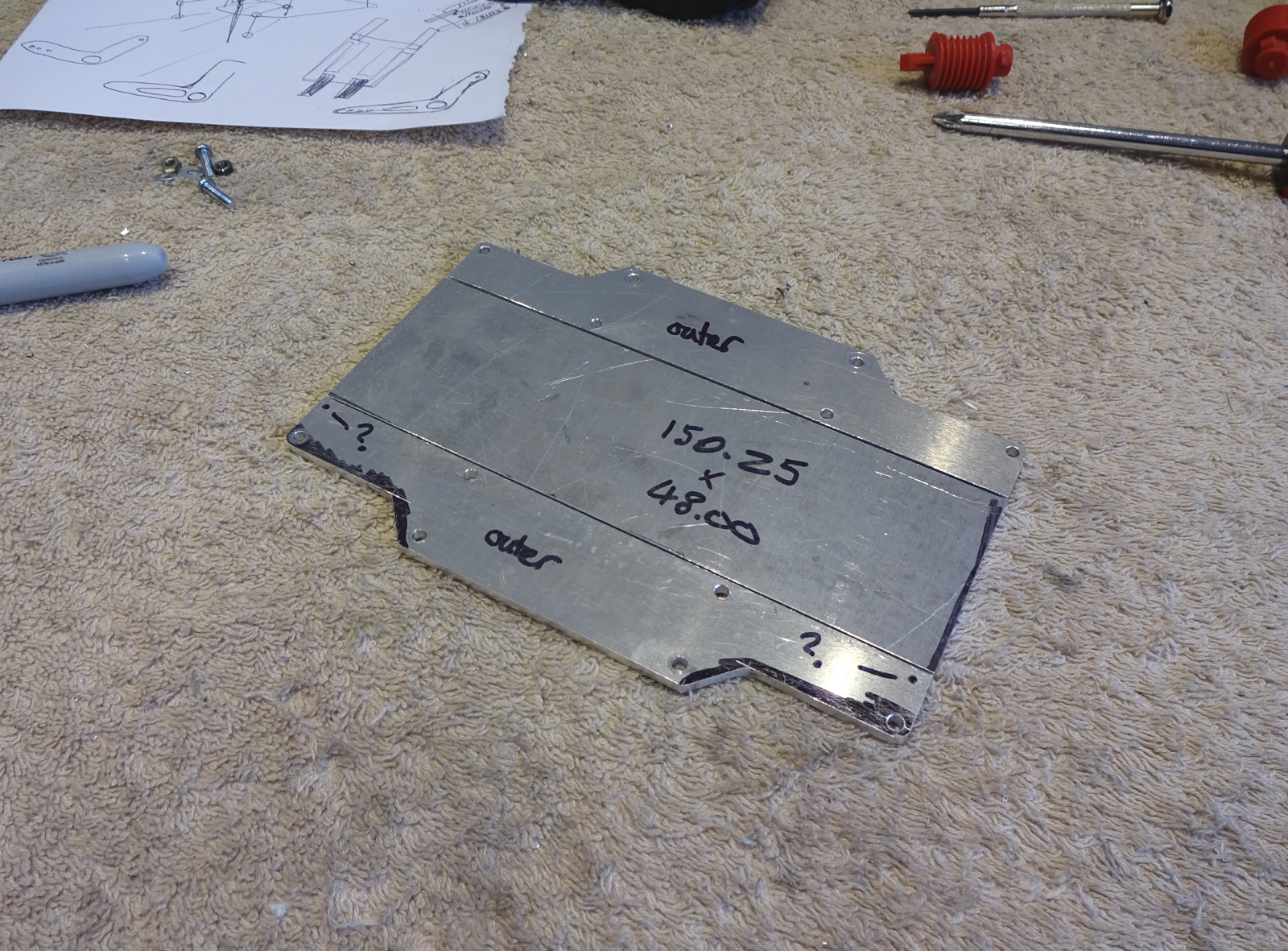 Clamped it to a piece that will become the top deck, holding it like this I can mark with a drill through the existing holes to line it up. 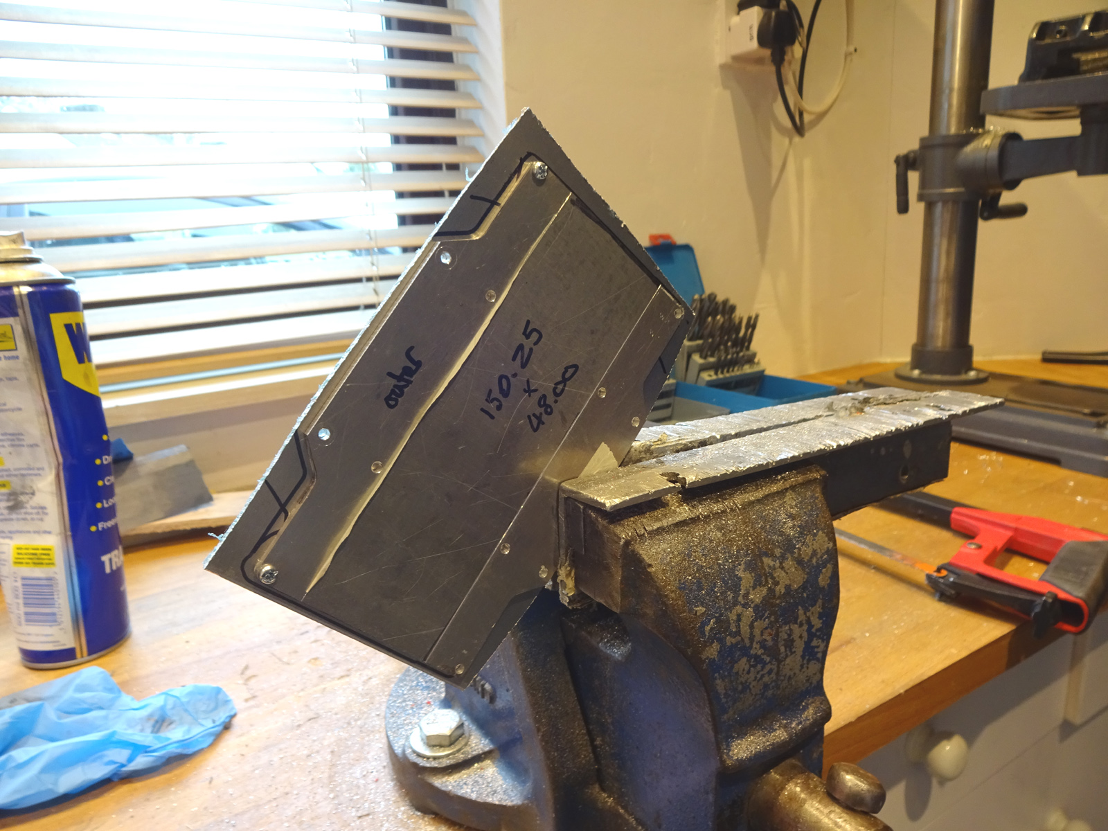 Then I couldnt be sure about the top deck shape, so I had a cup of tea, and gave up 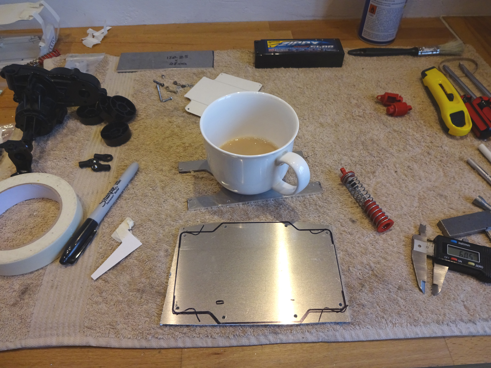 Ok after some thinking I have the top deck sort of where it needs to be, the cantelevers are going to be at an angle. 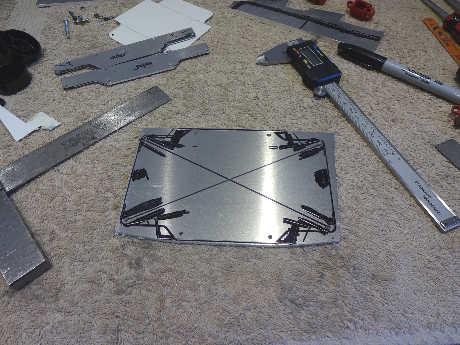 Need another one of these for the other end. 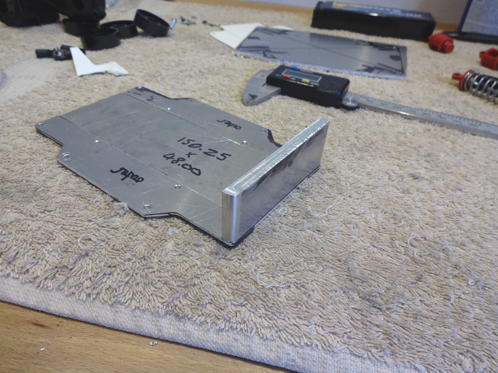 Cut the inside of the link out and flattened the top to give the rod end more room to move 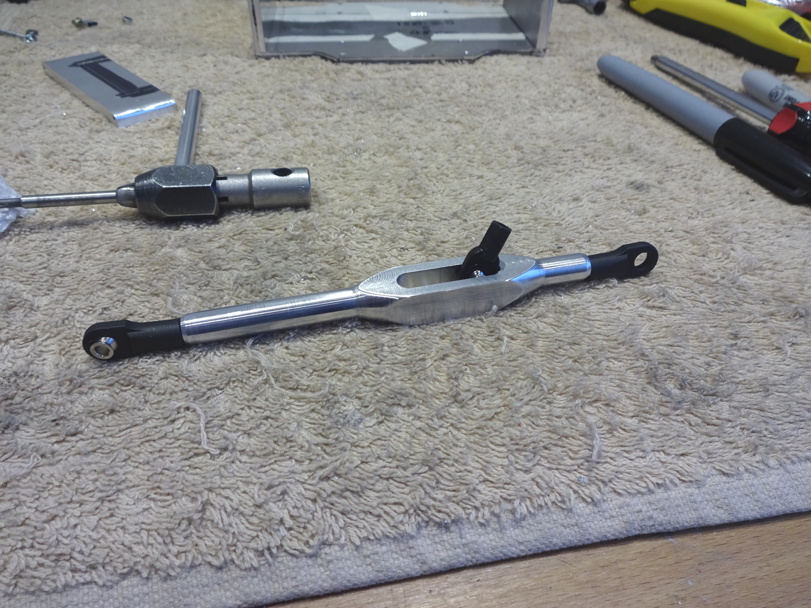 now just got to make 3 more just like it 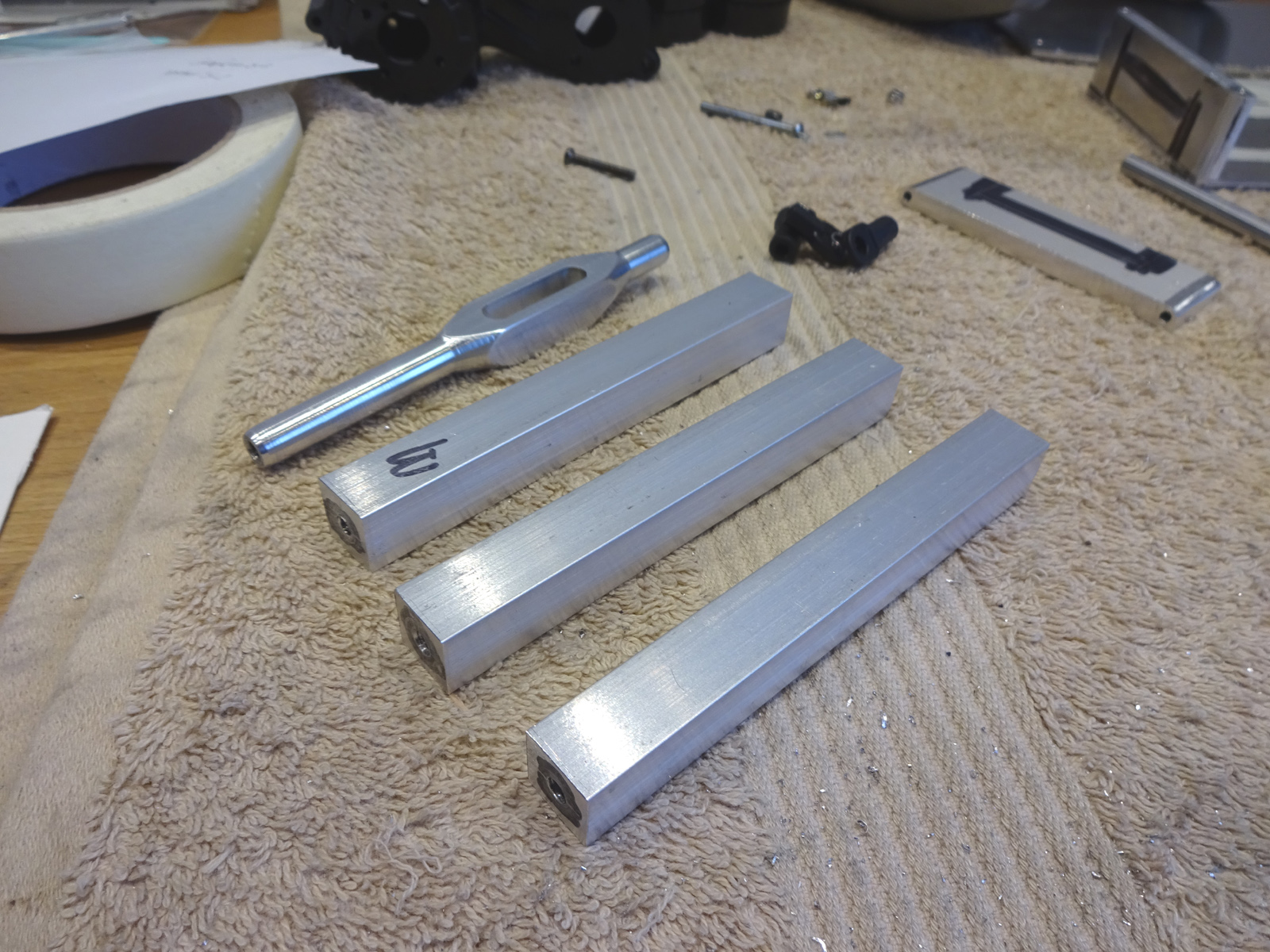 setting up on my little lathe 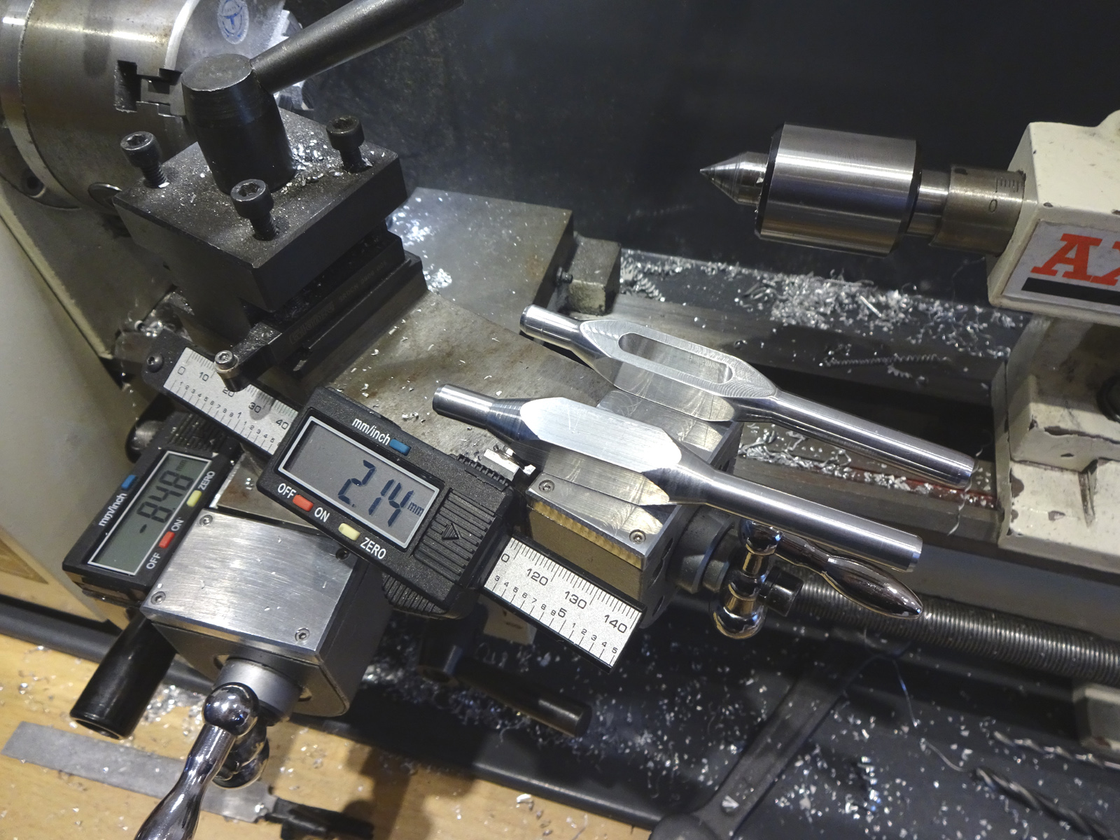 all the bodies turned up nice 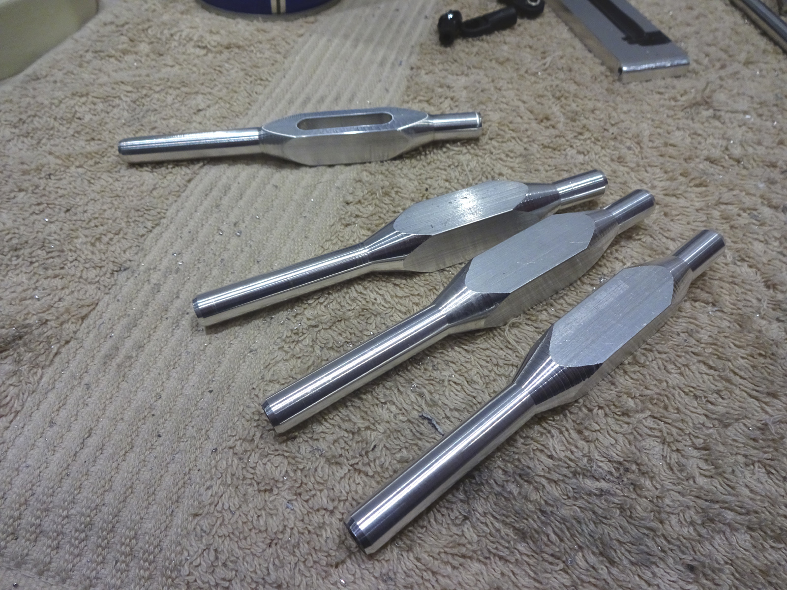 put the flat on the top and made the hole for the rod ends. 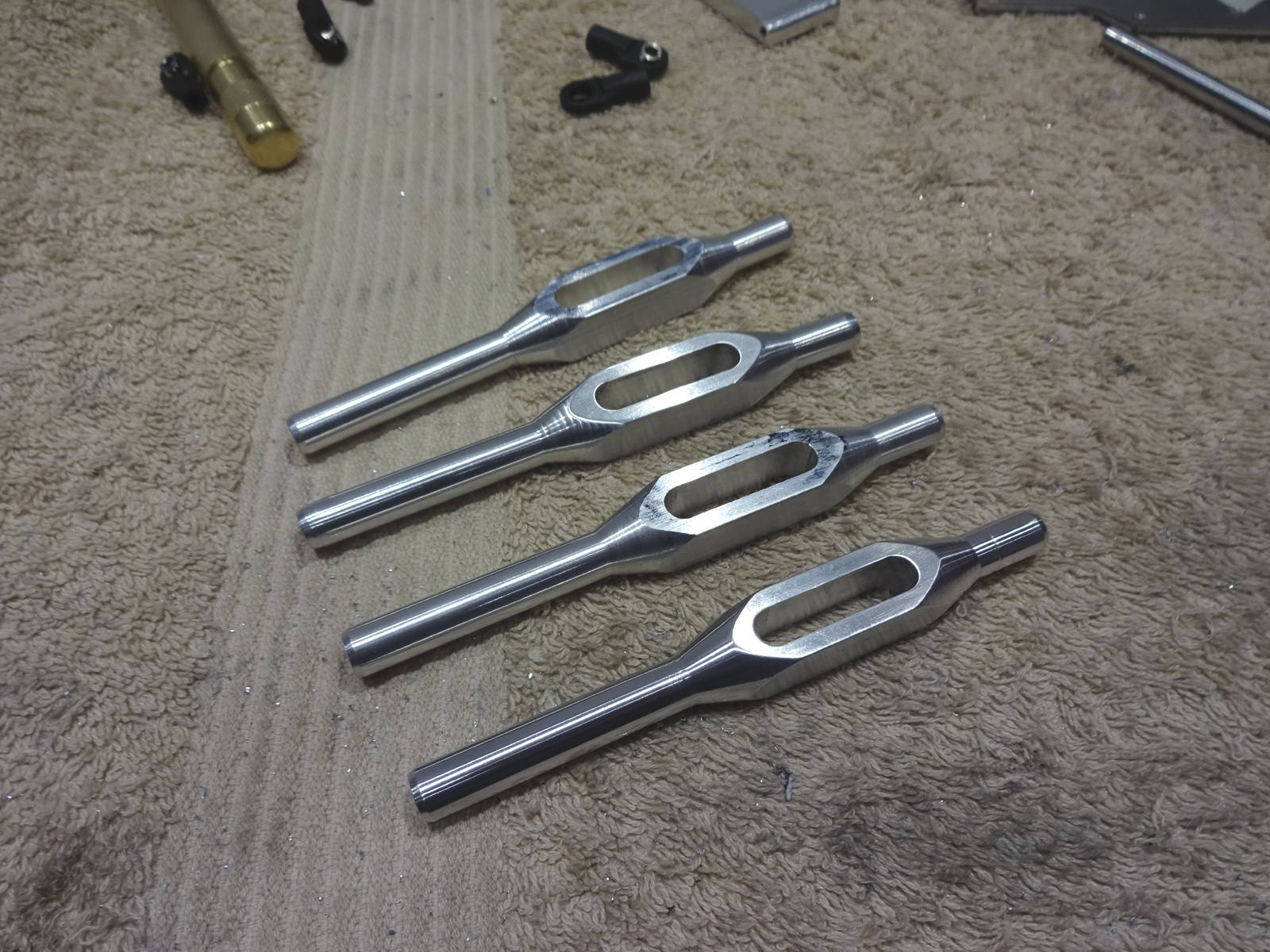
|
|
#3
07-06-2018
|
|||
|
|||
|
Back to the chassis, made another side and then the middle deck..... which may or may not be the right size.
 Cut slots out of the sides and then new sections to attach to the battery tray. 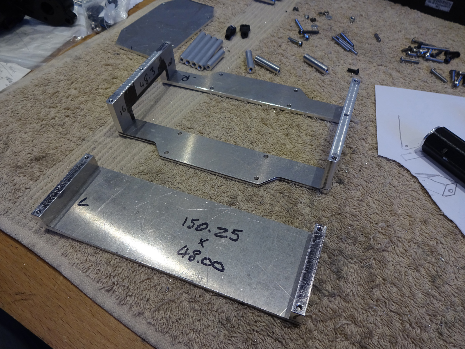 so you can put the battery in the tray then load it from the bottom. 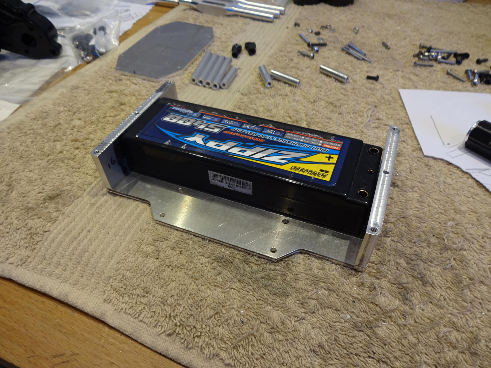 Some standoffs for the top deck, again, maybe 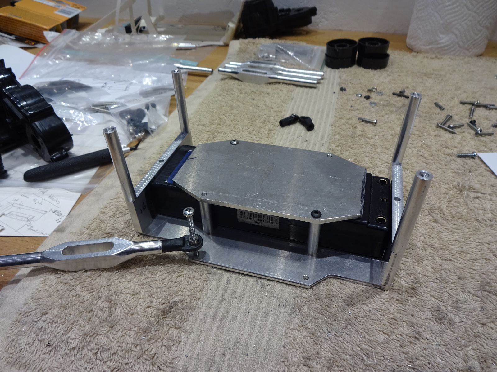 Ok, cantilever time! this should be fun, using 8mm thick, cut the rough shapes out with a hacksaw first. 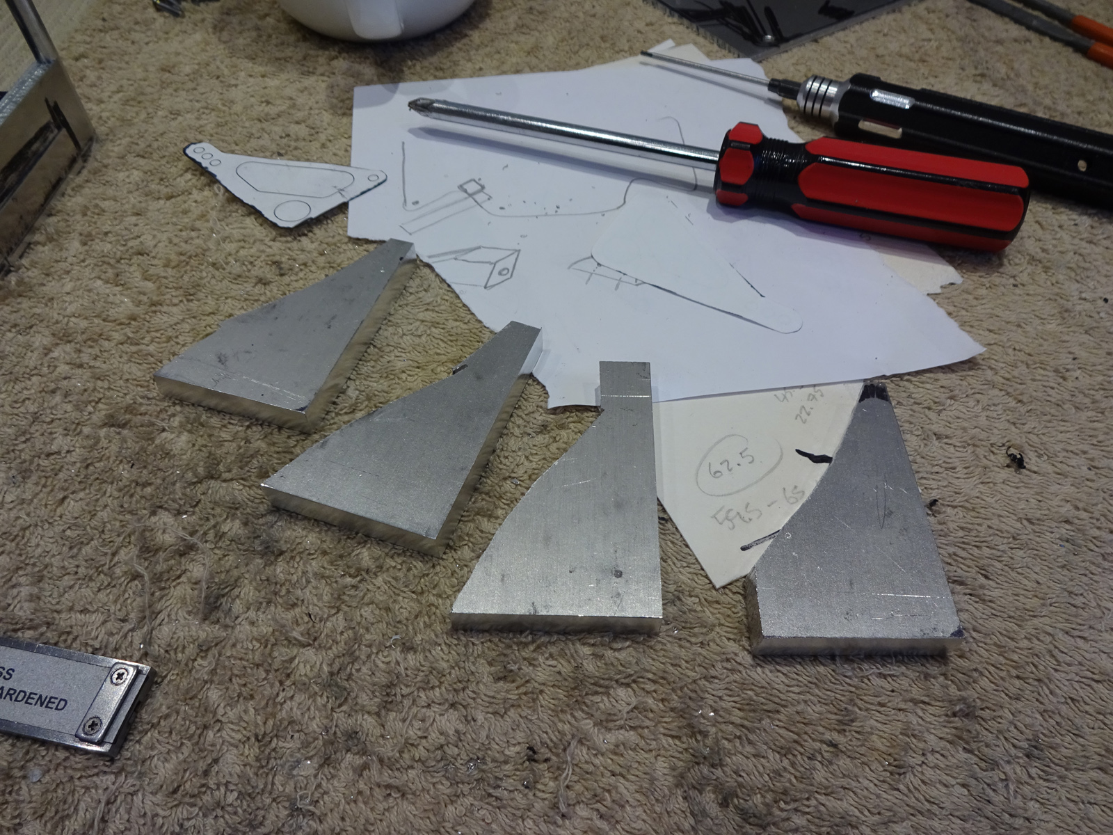 Drilled one of them with the 3 holes where I wanted, then through them all in one corner in the same place and then bolted them together and drilled the holes through them all. With them all together like this its a lot easier to get them exactly the same and also much quicker. 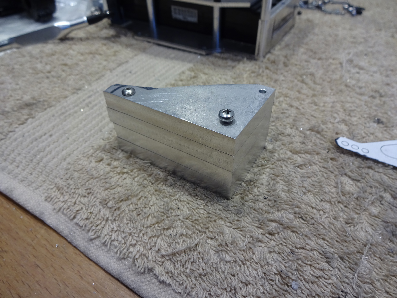 Machining the flats on them and buzzing off the corners just to make the process of filing the radiuses a bit easier. 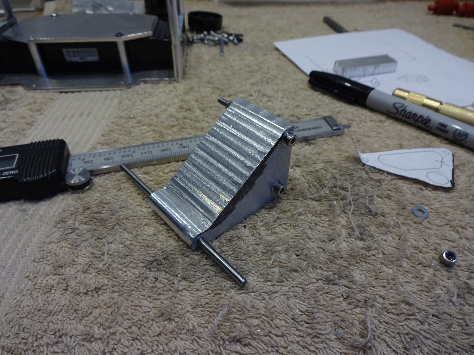 Trimmed all the corners ready for filing 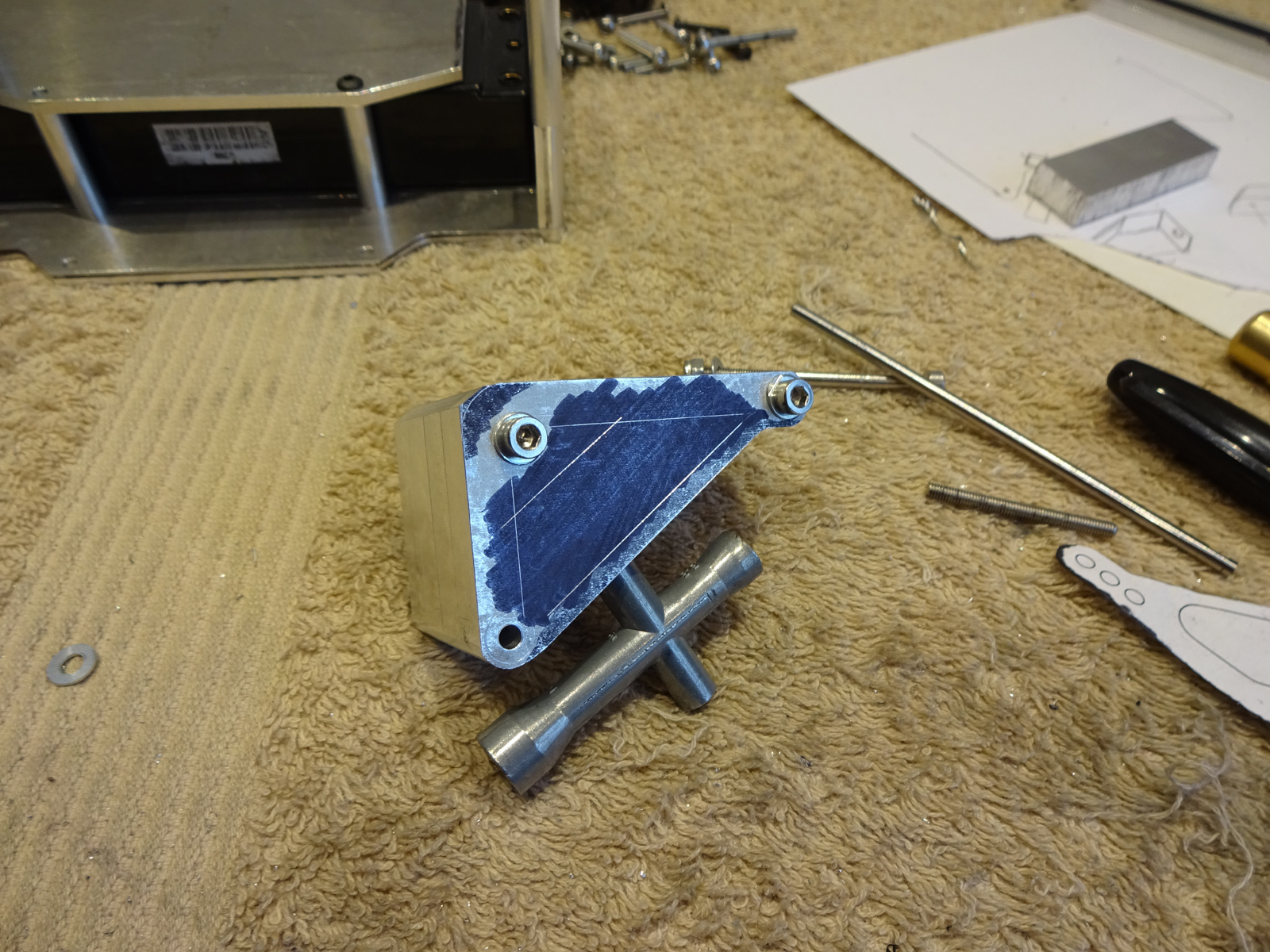 Split them into 2 lots of 2. They are 8mm thick, so machining the middle hole is ok for 16mm thick but trying to do all 4 at once would be a bit difficult. This poses its own problms, I have to cut up and down and then left and right making a note of where I start and how far I cut in each direction. Then I have to unclamp it and re-clamp on an angle to do the other 2 edges, again noting where I start and stop so when I do the other 2 I can do it exactly the same. 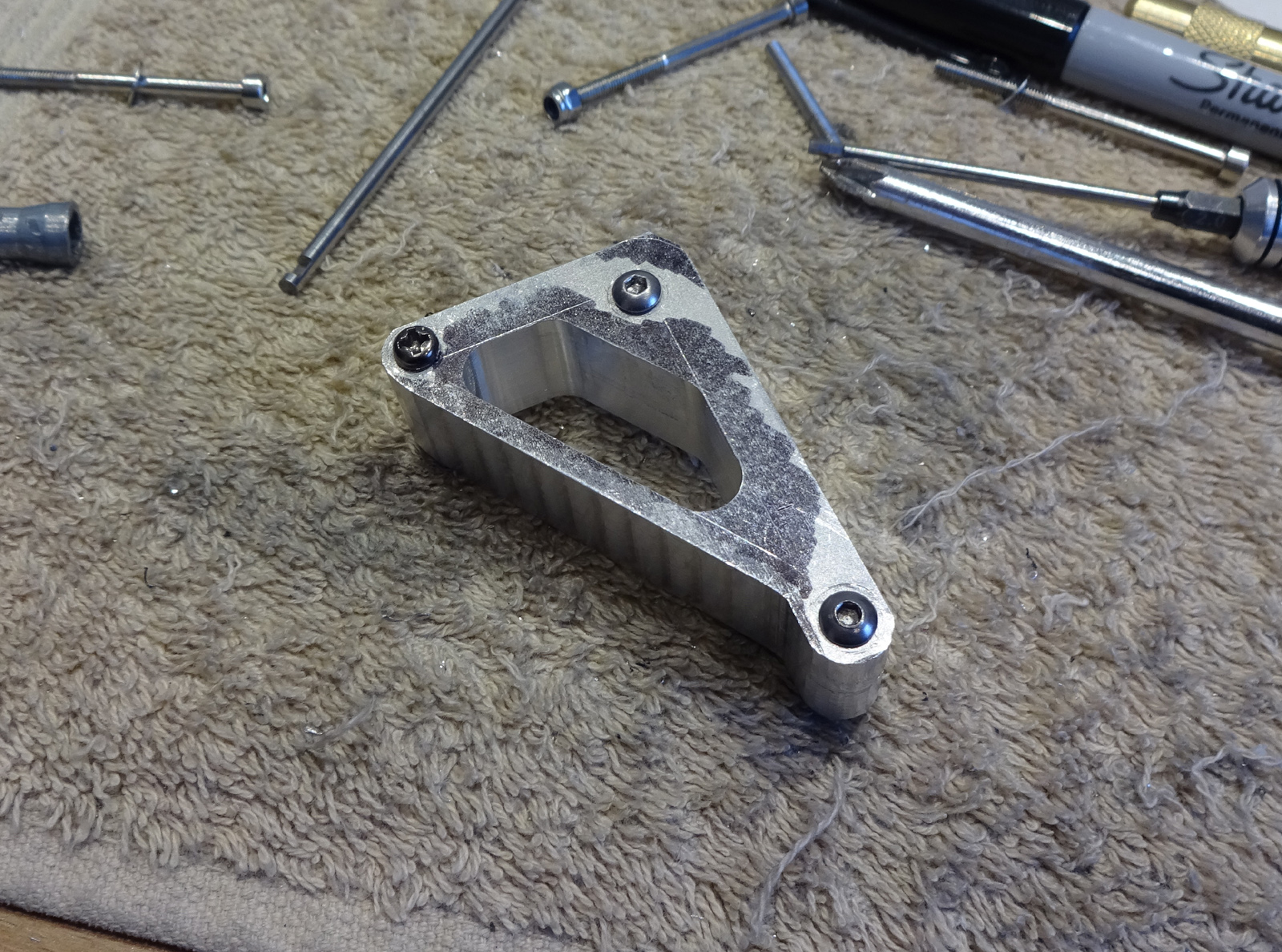 work in progress, clamped in position to do the up/down, left/right. 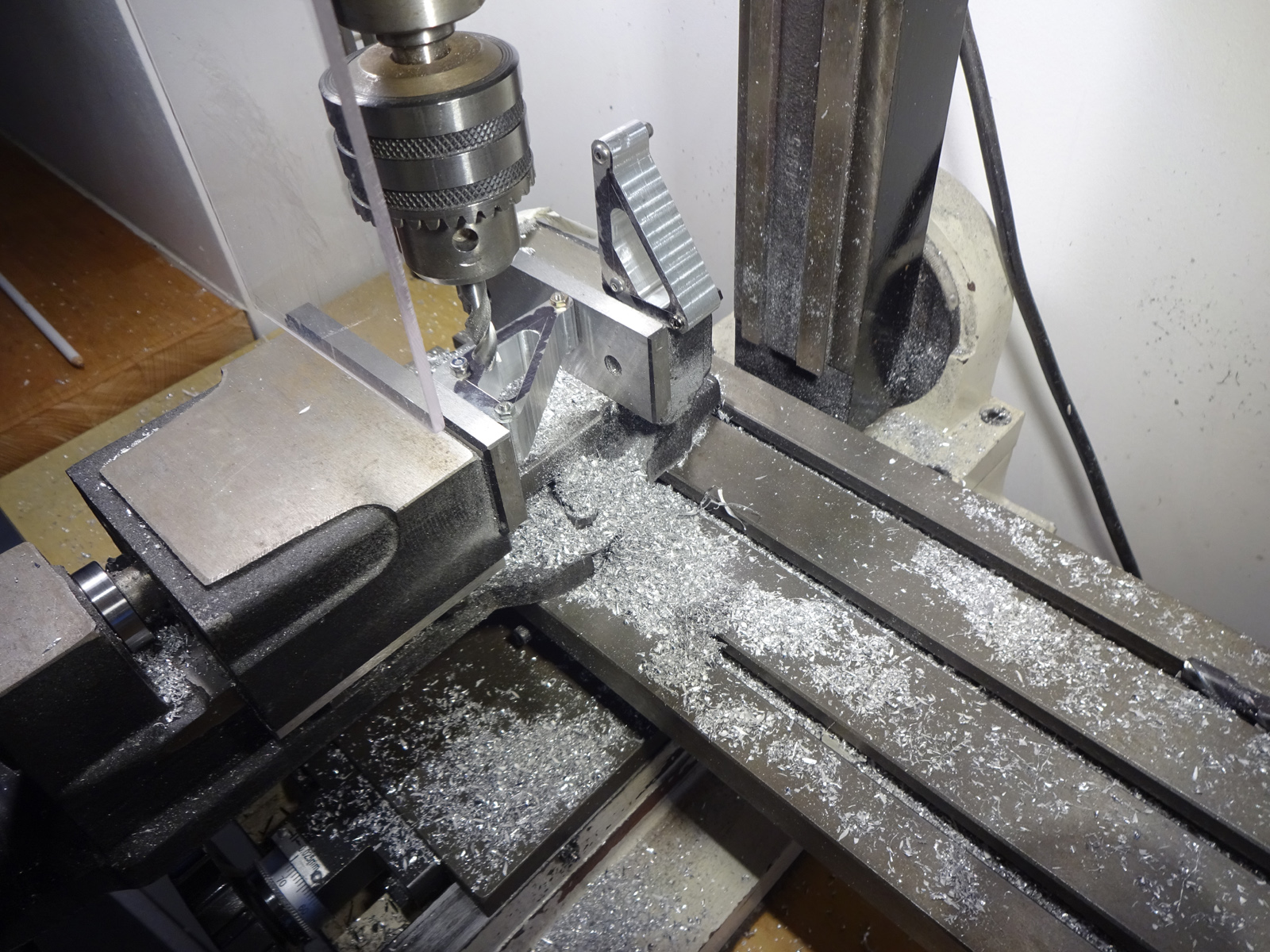 Drilled the hole for the bearings very carefully, then set it up in the mill and milled a 9.5mm hole. Next using my new tool, a reamer, no idea how I have got this far without owning any reamers before I reamed the hole to a perfect 10mm so the bearing just presses in. 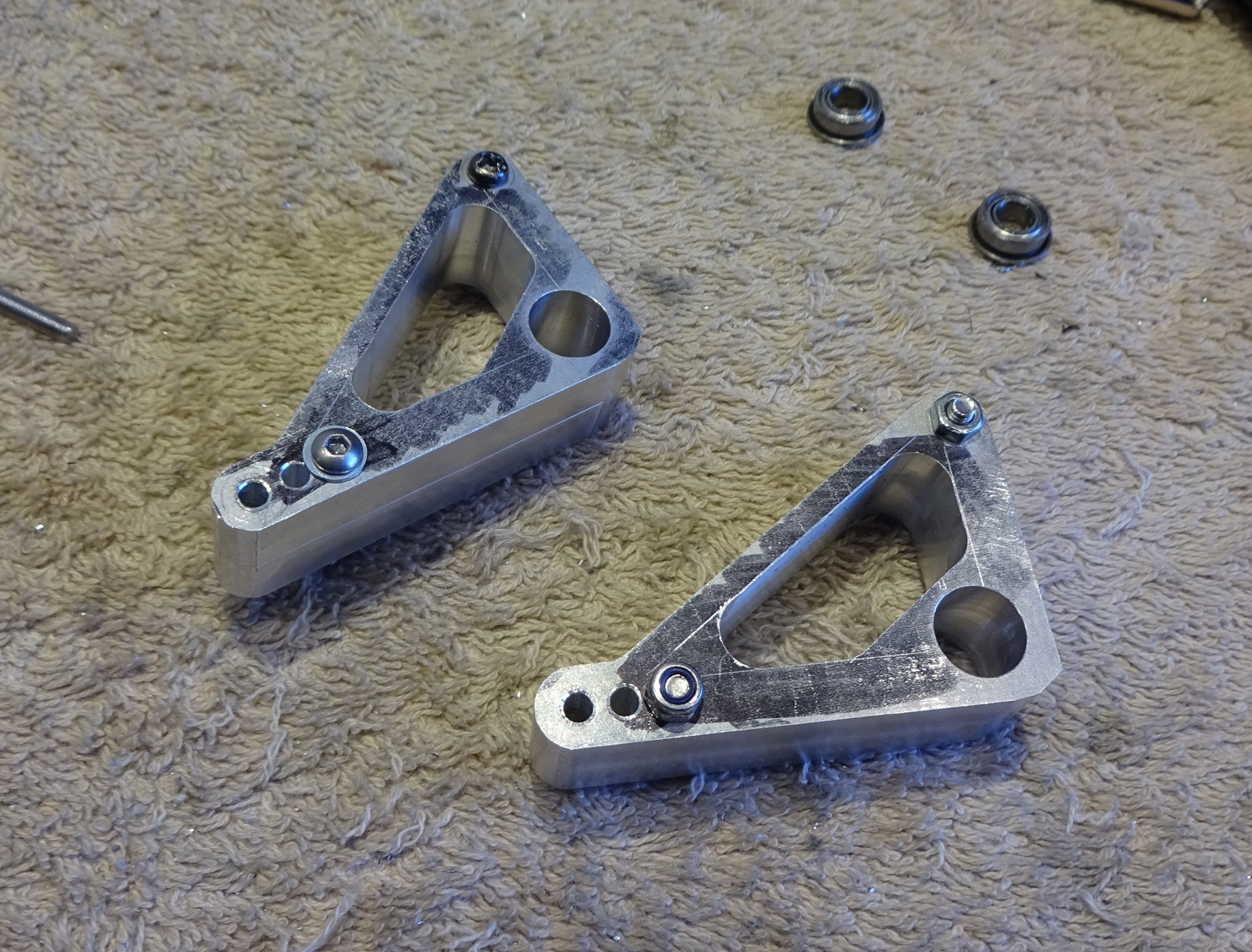 now its time to seperate them and give them a quick scrub wth some 1000 grit to see what we have. 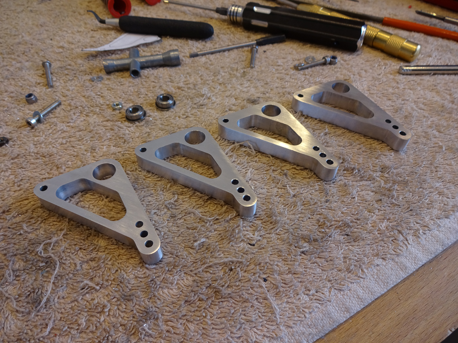 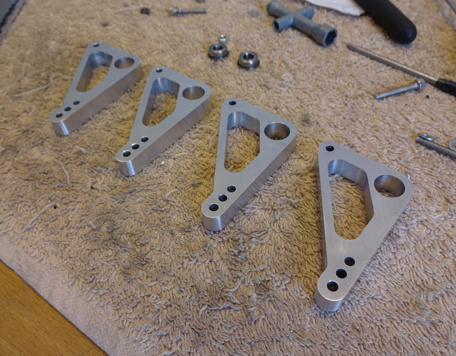 really pleased with these, they look and feel proper. Next up I wanted some sway bars running on bearings, this will be attached to the middle deck of the chassis. 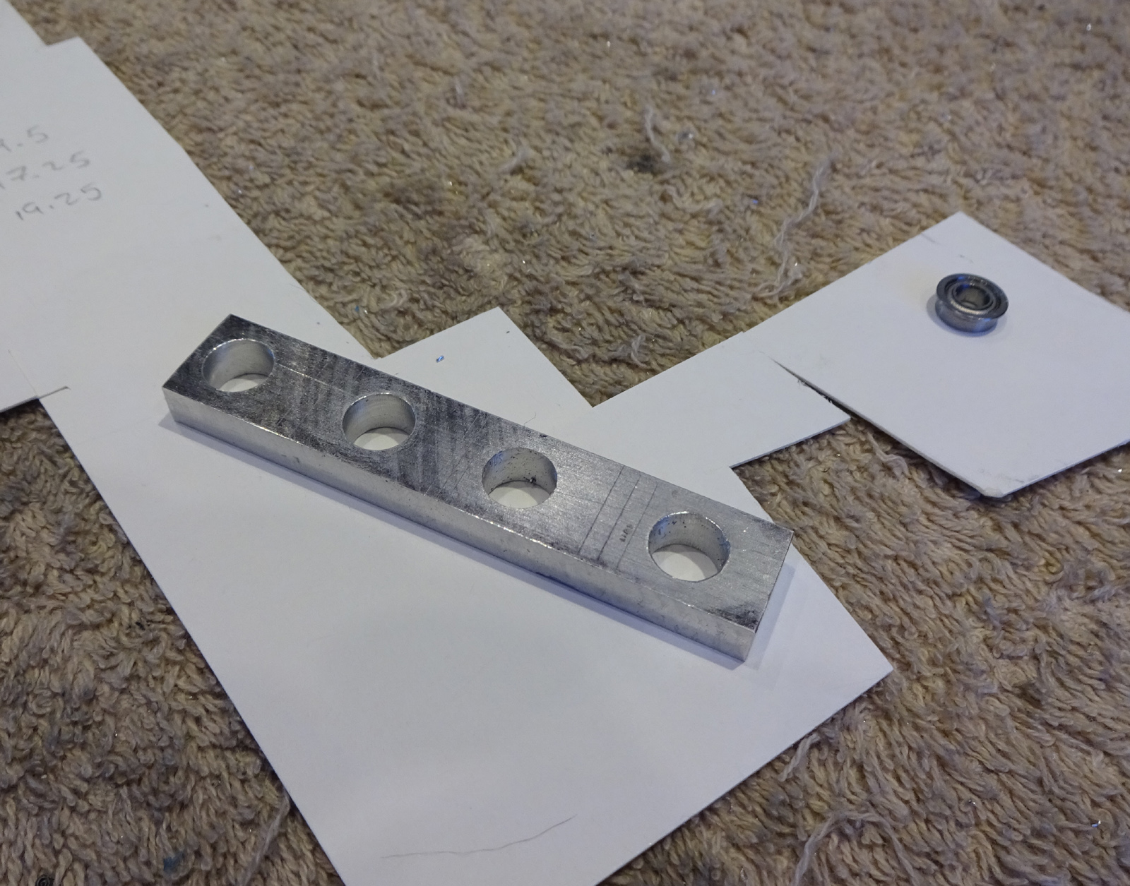 I set the strip up in the mill then just worked my way down boring the holes and then did the last 0.2mm with the reamer to get a perfect 6mm for the flanged bearing to press into. Cut them up and flattened the faces, then drilled 2 holes in the bottom of them all. 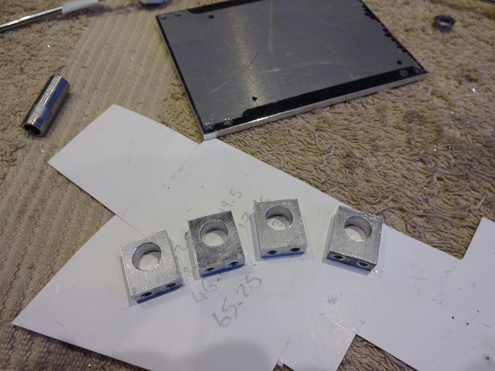 Curved the tops, mmmmm smoooth 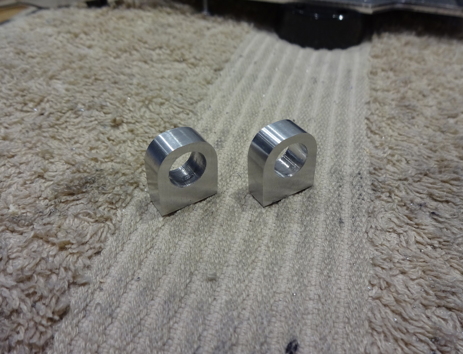 Wasnt until I came to fit them I realised my middle deck was totally the wrong shape, So I had to make a new middle deck with some nice little wings for the mounts to sit on 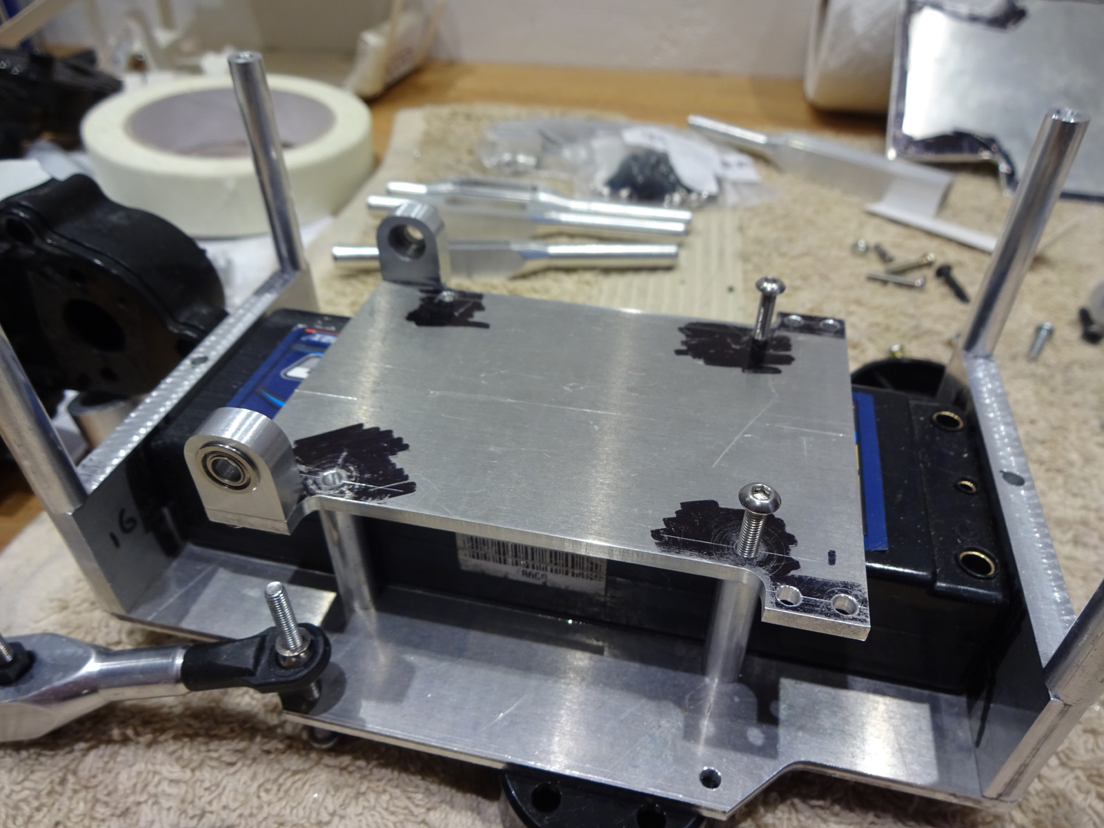
|
|
#5
08-06-2018
|
|||
|
|||
|
Yeh, I did a similar thing using AR60 axles, the thread is on here, but I got fibrelyte to cut the chassis plates for me.
These are going on the ends of the antiroll bar and hold the rods that go out to the lower wishbones: 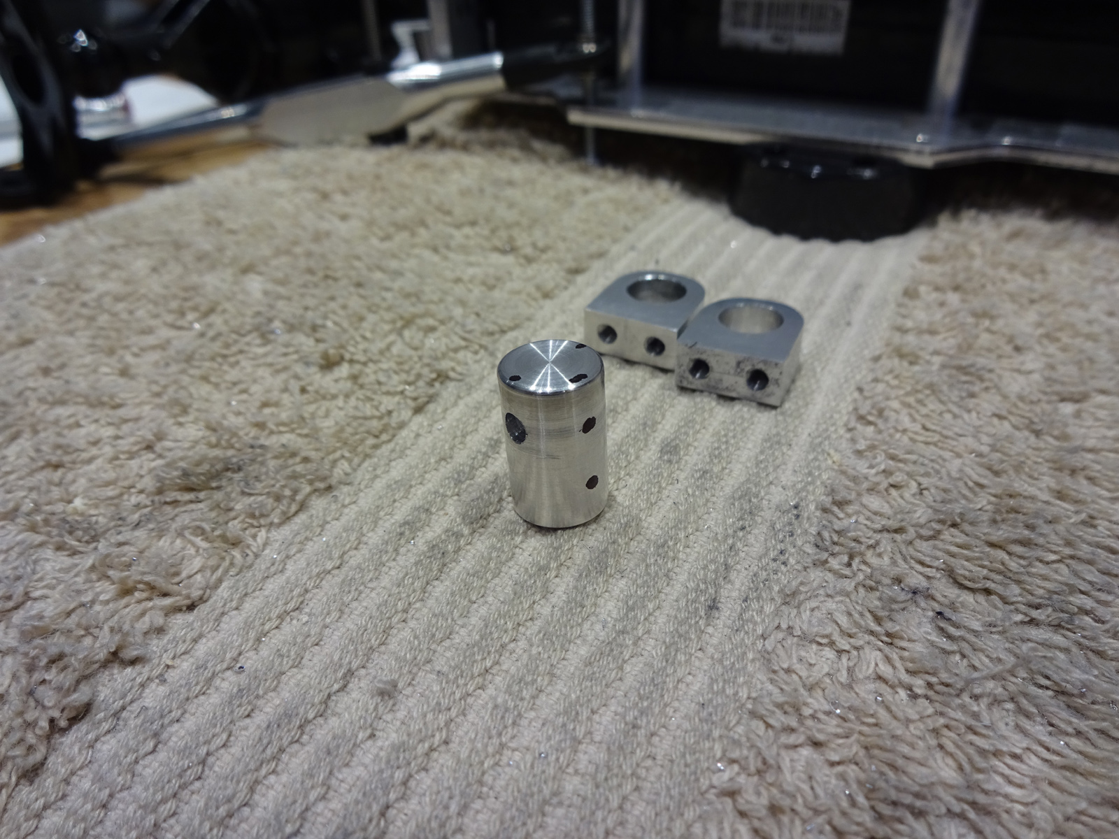 drilled them all with holes at the same angle (harder than it looks) 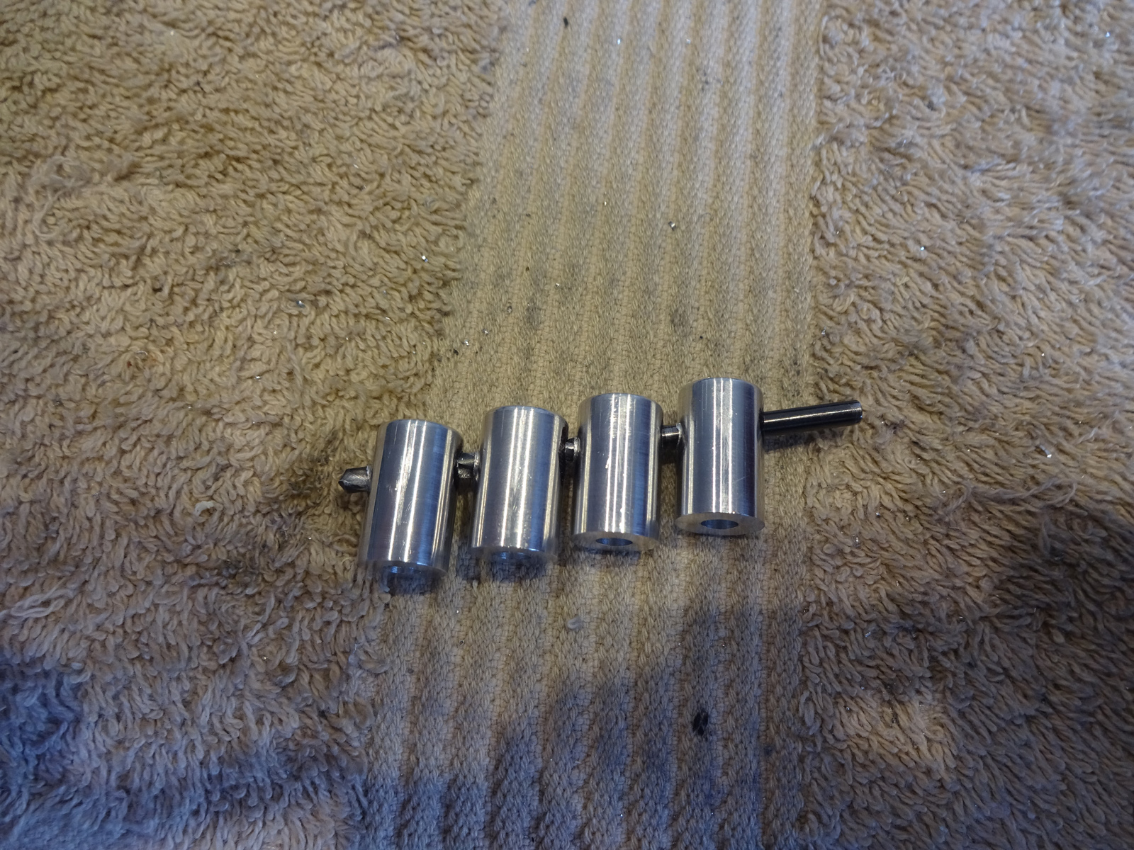 and they fit like so 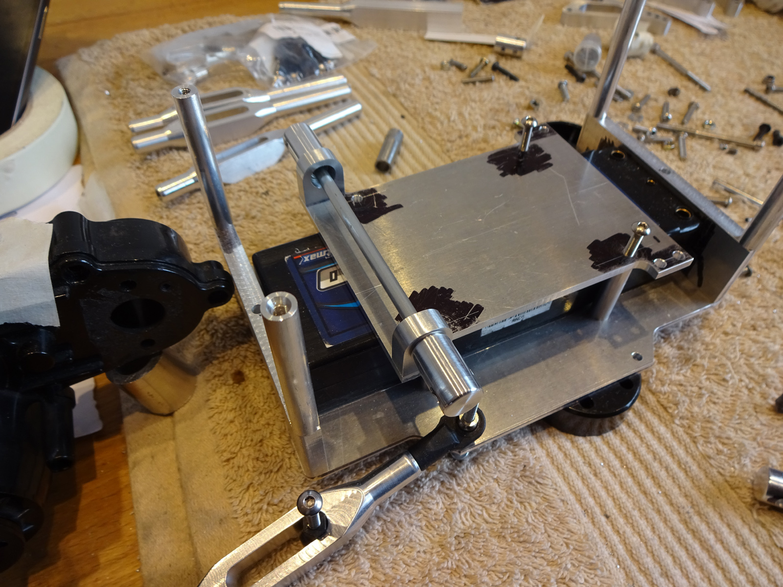 Did a bit of work on the top deck, I originally filed the curves by hand wich is rubbish so I set up a little jigg on the mill so I could cut the same angle on all 4 corners.  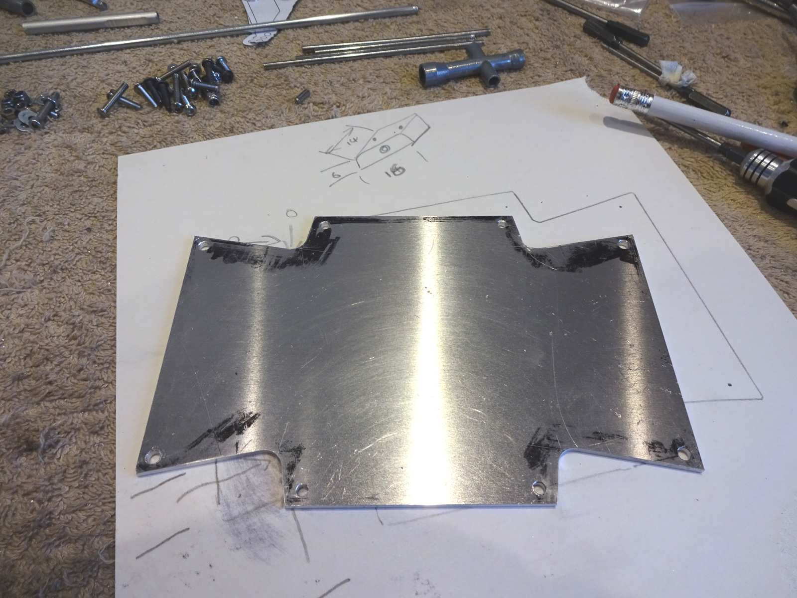 thats it for a couple of days
|
|
#6
08-06-2018
|
||||
|
||||
|
Awesome work. Will be great to see it finished......

__________________
http://www.oople.com/forums/showthread.php?t=83767 TRADER FEEDBACK **** 5 Metres Speed Swimming Champion 1976****
|
 |
|
|


 Hybrid Mode
